|
Scintillatin'
Saucer, by Larry
Conover
Click the image to view or download the half-size
plan.
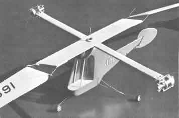
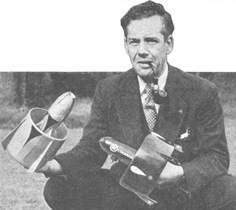
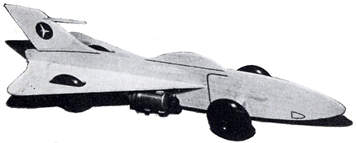
  Larry Conover
design for a 13-inch [33 cm] flying disc
powered by twin Jetex 50 engines. This
model launches from a pinwheel
pedestal. It's described as an
"all-weather flyer." Maybe the answer to
windy day flying sport in New Mexico?
The article, from Flying Models,
has this to say:
Larry Conover
design for a 13-inch [33 cm] flying disc
powered by twin Jetex 50 engines. This
model launches from a pinwheel
pedestal. It's described as an
"all-weather flyer." Maybe the answer to
windy day flying sport in New Mexico?
The article, from Flying Models,
has this to say:
Werner von Braun, the NASA, and also
the Russkies will take a back seat when
you FM fans launch this sizzling
satellite. Back in the fall of
'51, reports were going around that
had the local milk brewers reaching for
their shotguns. The U.F.O. scare was in
full swing. Eyewitness accounts from the
pasture on the south forty indicated that
Old Bossy was kicking up her heels at a
new kind of flying pest. So
...
I was forced to move saucer testing
operations into the hills. It was just
as well. Some of the early models, upon
reaching maximum rotational velocity,
would disintegrate in
mid-air.
Here is a typical test run of saucer
No. 2. Jetex engines loaded and mounted.
Starter punk smoking. Wind SW at two mph.
Fire one! Fire two! Pull fuse wires. Slow
rotation begins. Then a rapid increase as
the engines build up pressure. BLAST-OFF
in five seconds after
firing.
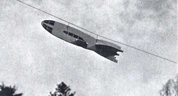
The test vehicle has risen from the
launching tower, and ascends at a
steadily increasing rate. Blue exhaust
smoke funnels down from the center.
Slight drifting off course. Altitude,
seventy-five feet. One hundred. One hun
-- WHAM! Oh oh, somebody pushed the
panic button.
Launch is from a low
tower
What was once a carefully
engineered maze . . . Now is shattered
sticks and paper tumbling down to earth.
Back to the drawing board.
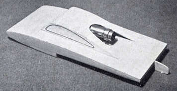
All that's cleared up now.
Installation of a "panic wire" holds the
two engine mounts together. It takes
loads imposed by centrifugal force at
high rotational speeds.
Click image for half-size plan
 |
Ready to start your space-saucer?
Ok, find a gallon jug. And, after
cutting several strips of 1/16 x 3/8
medium balsa (long grain A stock), soak
them in water for ten minutes. Then wrap
them carefully around the jug and let dry
overnight. If you are in a hurry, bake it
in oven at 250 degrees.
While you're waiting, cut out
thirty-two lift vanes from 1/32 light C
grain balsa.
Take note: the lighter the craft,
the higher it goes. Draw the two
circles, using compass shown on plans.
When laying down the rims, place pins on
either side of the balsa, not through
it. Outer rim is longer than three feet,
so use two pieces and join them at engine
mount positions. Tailor the distance
between rims by placing lift vanes at
intervals around the circle during
pin-down operation.
Install the vanes, and go easy on
the glue. Best to thin it out with
acetone. Measure positions for the first
two vanes, but after that just "eyeball"
them in. Next comes the center fan.
It's just a plain four-bladed built-up
indoor prop. Follow the plans. Make sure
all your blades are right hand, and match
the direction of the outer vanes. A
large pinhole in the center is reinforced
with bead bearings, well cemented. This
must be strong.
The engine clips are glued and
screwed into place, being careful to
point each one in the proper direction.
He sure to bend the tops over (check
plan) to prevent engines flying loose in
mid air. Install the "panic wire" by
drilling a small hole in the center of
the engine clip. Bring the wire through
and wrap a turn around the mounting
screws. The wire should stretch tightly
between the two mounts and pass on the
under side of the prop
blades.
A small piece of aluminum foil
should be glued to the rim in the exhaust
area.
Cover the top only of the prop
blades with light tissue. Two coats of
thin clear dope, with none on outer
blades. Last operation, balance saucer
with engines out. Use wire for axis.
Hold ship vertical and give it a spin.
Place a bit of clay opposite the heavy
side.
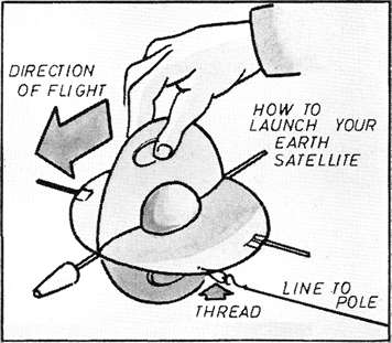
No need to construct a launching
tower for first test. Place a 0.032 wire
axis in the end of a stick. Hold overhead
after lighting fuses. Do not release
until you are in orbit.
To insure successful launchings:
Load engines carefully. Make one fuse
longer, so both engines fire about the
same time. Always use a punk, or piece
of DT fuse for lighting. Pull fuses on
the dot. When flying in the wind, give
your saucer a booster spin to help get it
going. Stand back. It skims low
downwind for the first fifty
feet.
On a quiet evening your snappy
satellite will ascend to 300 feet
directly overhead, pause lazily at the
top, reverse direction, and spin gliding
down like an aerial elevator. If saucer
fails re-entry as programmed, notify Bob
and Ray, Lost and Found Space Vehicles,
Interstellar City, Earth.
From Flying
Models publication "A Decade of
Designs II, 1956-1966".
Rob McConaghy, who, as a 13-year-old, built and flew a Scintillatin' Saucer, recounts his experiences:
I built the flying saucer from plans bought from Flying Models of December 1959. The saucer used two Jetex 50s mounted diametrally on an approximately 12" O.D saucer made of balsa. Principal lift was from a number of (24? 32?) 1/32" thick balsa blades about 2" long X 1/2" wide between two concentric laminated bands of 1/32" balsa, laminated to 1/16, I think. The engines were kept from flying apart with a diametral .016 or .032" dia length of music wire. One was asked to build a 3 foot high launch tower of balsa sticks with a central music wire pin at the top, from which to launch the thing, but I cheated.
As you might expect, lighting and pulling the copper wires out of the two engines simultaneously was the big challenge. I had several thrilling flights – and several failures – all in one day – before all was busted, but I was thrilled, and happy (having the free flighter mentality).
At the time, I was terribly disappointed that the aluminum housings melted at the gasket joint (shades of the space shuttle). The housing rims melted through locally (along about a .10 " perimeter length, max), not all around the perimeter. This was my first in-your-face, no doubt about it, example of design flaws (I am a mechanical engineer, and have contributed a few over the years) but I did not even begin to think of complaining to the manufacturer (a universe away, in imagination and worldview at age 13, and untouchable), and set it on the shelf with all the other disappointments of the day – pathetically weak magnets, glues that didn't work (remember "Iron Glue"?), crummy batteries, bicycle generators that would sap all your strength to light a 3W bulb, etc.
|