From
Model Boat Book (1948), Chapter Thirteen
(contributed by Roger Simmonds who says, "I built copies of this model continuously as a boy,
reduced for 50B (the model, not the boy)".
A JETEX POWER HYDROPLANE
The application of rocket or jet propulsion for model speed boats is an interesting development, the more so in view of contemplated record attempts on water with this type of propulsion. With the coning of the small and handy propellant cartridge and suitable units to contain them, developed and marketed by Messrs. Wilmot Mansour, it has become quite feasible to build quite small models for "jet" propulsion. Provided that the craft are properly designed and constructed, excellent speeds may be obtained, quite out of proportion to the size of the hull for durations of well over half a minute.
The Hydrojet, designed by M. C. Cowell, for Messrs. Wilmot Mansour & Co., is a typical and successful design and building instructions are given in the following pages.
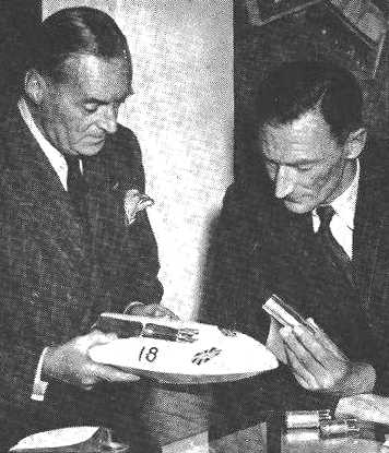
(Below left) The late Sir Malcolm Campbell, holder of the World's Water Speed Record, examines the Hydrojet with interest.
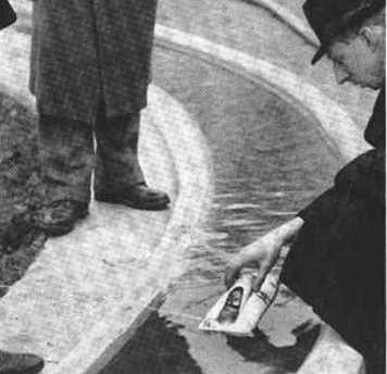
(Below right) The Jetex-powered Hydrojet ready for a tethered run on a circular boat pond. The fuse is lit and the streamlined cowl replaced.
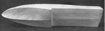
(Below) The correct flare forward of the step is obtained by diagonal planking with 1/16 in. balsa strips.
The backbone of the Hydrojet is the 3/32 in. plywood hull. This must be cut out with great care, preferably by means of a fine fretsaw, leaving sufficient margin to allow for cleaning up to final size with sand paper. The slots for the frames are best cut out with a warding file, and it is advisable to keep these carefully within limits, it being easier to enlarge them as and if required, than to build up the boat with loose fitting frames.
Cut and fit frame No. 4, of 1/4 in. balsa, cementing it firmly to the keel and checking that frame and keel are at right angles to one another. Frames 1, 2 and 3 can now be cemented in position, ensuring that the interlocking slots in frames and keel are right home and again checking that the frames are parallel to frame 4. Now cut out and fit the port and starboard chines, the 1/8 in. by 1/4 in. curved pieces which run from beneath frame 4 to either side of the bows. Cement these also to frames 1, 2 and 3.
Frames 5, 5a, 6, 7 and the 1/4 in. transom can he cemented in place, followed by the after chines, port and starboard, which are cemented under each frame and the transom, being cut off at the correct angle to be flush with the latter. Cement two 1/8 in. by l/4 in. balsa battens across the back of frame 4, either side of the keel, with their bottom edges flush with the bottom of the after chines and the lower edge of the keel. These form the forward supports of the after floor.
The 1/8 in. square obechi stringers can now be fitted. Two stringers run from frame 3 aft to the transom, and a single centre stringer runs forward from frame 3 to frame 1. When these have set, cut them off flush with the transom angle and bevel off the edge of the transom to blend with the lines of the stringers.
The after portion of the floor can now be fitted from the step to the transom, 1/16 in. sheet balsa being well cemented in position round the edges and to the keel. The floor is not flat, but is very slightly "V"-ed upwards from the keel to the chines.
Forward of the step the hull has a clearly pronounced flare, and the sheeting must be very carefully done in order to maintain the lines accurately. Note that the covering is applied in narrow strips of 1/16 in, sheet having the grain lengthwise, laid in "arrow-head" formation towards the bows. Reference to the drawing will show how this should be done. Use plenty of cement in the keel joint and when set, sand smooth on the underside, at the same time shaping the plywood keel to a knife edge.
Fit the blocks of obechi as shown in the drawing, one pair either side of the keel just forward of the transom, for securing the rudder plate, one slotted block fitted over the keel ahead of frame 5, and a similar but deeper one ahead of frame 4. A platform of 1/16 in. sheet is cemented over the two latter blocks, running from frame 3 to 5a, and sheet sides fitted, curving inwards at the front. This is the mounting platform of the Jetex unit, and the "box" thus formed is completed by lining with protection asbestos paper.
The "skin" of the hull can be tackled next. This is again of 1/16 in. balsa sheet, laid on in narrow strips from frame 1 to transom. Leave the Jetex platform uncovered, also the space aft of the platform, between the stringers, which is covered with thin tinplate. The nose is completed by cementing balsa blocks either side of the keel, sanded to blend into the hull lines.
The hood for the cockpit is made of 1/4 in. balsa sides and top, with the hood frame at the forward end, and fitted over this is a transparent moulded cover. This is shaped over a wooden former, by gently heating the transparent sheet and moulding it over the former by hand, finally trimming off the surplus with a razor blade.
The hull is now ready for covering with tissue. This should be doped on, using three sheets to cover the underside (two pieces for the forward portion, and one aft of the step). The upper hull is best covered in strips, overlapping these about 1/16 inch. Smooth the tissue on with the fingers. When quite dry the whole hull is lightly sanded with fine grade sand paper, and given two or more coats of coloured dope.
Finally fit the rudder with woodscrews into the obechi block, and screw the Jetex mounting bracket to the blocks under the mounting platform.
For those who wish to run the Hydrojet on a circular course round the pole, attachment eyes should be made up front 20g. wire, the after hook being fixed at the transom and the forward hook in the block balsa nose, on the opposite side of the plywood heel-piece to the pull of the tether. A triangular bridle of strong packing thread or light fishing line is advised. The central tethering point should be kept as low as possible to avoid any undue tendency for the inside of the boat to lift at speed. The position of the rudder must he found by experiment, depending on the radius of the course, but for a start the rudder should be set to keep the tether fast, by giving the boat a light run-out from its true course.
When operating the Jetex unit for the first time, remember that considerable heat is generated, and allow the casing to cool off before attempting to remove it from its mounting bracket.
Provided that a sufficient area of water is available. the Hydrojet can be run either straight or on a huge circular course without a tether, and considerable speeds should be obtainable under these circumstances as the boat is stable and has excellent lines for high speed planing. For maximum efficiency the hull should be trimmed so that at full speed the boat is skimming on the edge of step and the rear edge of the transom, surface tension being actually broken between step and transom.