|
Jetex Rocket 50-HT
Note that photos of
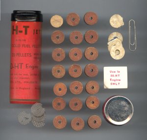
the Jetex 50-HT engine are shown on the Jetex 50 series page. The
Jetex 50-HT fuel pellets have the same
composition as other Jetex 50 propellants. A
1/8” central hole through the
longitudinal axis of the grain provides
increased burning surface, and consequently
greater chamber temperature and pressure, and
thrust. (Hollow-core propellant grains are the
norm in solid fuel engines for both tactical
and space missions.)
The standard Jetex 60
(single-spring) motor should not be used with
the more potent 50-HT fuel. Especially
designed for 50-HT fuel is the double-spring
chamber-sealer, combined with a steel-barreled
chamber. According to older Jetex literature:
“It is interesting to note that the new
fuel, despite its greater thrust and burning
heat, burns cleaner and actually reduces
maintenance.”
Early Jetex
literature also states: “Quick to spot
such possibilities as combining a 50-HT charge
with one of the lower-thrust 50 charges, one
for high acceleration and the other for
sustained duration, resourceful model designers
can work out many combinations tailored to
individual requirements. Additional variations
can be achieved by the different wick
arrangements now possible with the drilled
charges.”
When using the
recommended method of loading (where the
igniter wick is doubled in the pellets and
retained with gauze), a maximum thrust of 5
ounces [142 gm] can be expected with a burning
time of 2 to 3 seconds. Due to propellant
differences, firings may run as long as 3.5 or
4 seconds. If the gauze is left out, both
thrust and burning time will vary widely, with
peak thrust being reached more slowly and the
run lasting longer (but with reduced
thrust).
To attain more thrust
at the cost of reduced burning time, the wick
can be doubled and coiled on the face of the
top pellet, with a gauze fitted. Peak thrust
in this case is reached in a nearly constant
time of two seconds.
By combining one
cored and one plain pellet, with the igniter
wick doubled and retained with gauze, the peak
thrust is reached in about 1.5 seconds, with
the sustainer effect of the plain charge
extending the total burning time or motor run
to about 7 seconds.
The following is
reprinted from the original instruction sheet
provided with the first 50-HT engines sold by
American Telasco Ltd. [Notes in brackets are
ours.] Jetex Operation
50 “HT”
Reaction Motor: The only motor engineered to
take the new Jetex Super “HT”
fuel.
The Jetex 50-HT high
thrust jet engine has been designed
specifically to handle the higher temperatures
and pressures developed by the Jetex 50-HT
cored fuel pellets. Although its fully loaded
weight of half an ounce is no more than that of
the familiar 50-B engine which has been the
standard model propulsion unit for many years,
the 50-HT consistently produces better than
five ounces of thrust with a duration of up to
four seconds, using the cored 50-HT pellets.
This engine may the used also with the standard
50 solid fuel pellets for superior performance
and reliability, particularly in contest
flying. (The 50-HT pellets, however, MUST NOT
be used in the standard 50-B
engine.)
The 50-HT engine may
be loaded in several ways to obtain different
thrust patterns. When loaded with the standard
No. 50 solid fuel pellets it will produce
slightly higher and more consistent thrust than
will the 50-B, due to the tighter sealing
action of the double spring clips. This is
very helpful in contest flying; and is highly
important in the testing and trimming of any
model.
For testing of
vertical take-off designs, or for operating
such models from small flight areas, a
short-duration, maximum-thrust pattern may be
desired. In this case the setup shown in
Figure 1 would be used. Thrust and duration
will be similar to the left-hand peak of the
graph in Figure 2. Alternatively, by removing
the spacer and insulator disk and using a
stand-ard solid pellet, a low sustaining thrust
will be added to the thrust pattern. This is
shown in the right-hand section of the graph in
Figure 2. This pattern will be found useful
far gaining maximum altitude and duration with
swept-wing or delta designs--particularly under
windy or gusty conditions.
For maximum thrust
AND duration the fuel charge shown in the graph
of Figure 3 will be used. This is an extremely
high performance pattern which will greatly
magnify any maladjustment of the model. It
should not be used until after careful
trimming, balancing, and
testing.
Many multi-engine
combinations may also be worked out, using the
50-HT as a booster unit for high angle
launching or to gain maximum altitude. Because
of its very light weight and high thrust/weight
ratio, its effect on the wing loading of models
designed for larger engines will be of small
consequence. Due to its rapid thrust buildup
and short duration, the 50-HT engine should be
ignited after the main engine to eliminate any
possibility of lapse in effective
thrust.
Further information
regarding the design and operation of all types
of Jetex-powered model will be found in the
booklet “All About Jetex,” on sale
at your hobby store. ENGINE INSTALLATION
1. The mounting clip
should be securely attached to the model, using
both screws and cement.
2. The engine itself
must be held firmly in the mounting clip. Any
looseness should be taken up by bending the
ends of the clip inward to insure a tight
grip.
3. When the engine I
externally mounted, at least 1/4" [6 mm]
clearance must be allowed between the engine
and any combustible material. As an additional
safeguard the adjacent structure may also be
protected with metal foil or thin asbestos
sheet, attached with a non-flammable adhesive
such as water glass [sodium
silicate].
4. Internal
installations should allow 1/2" [13 mm]
clearance all around, plus protective
insulation. Also air venting of the engine
compartment is highly
desirable.
5. Behind the nozzle
some heat protection should be provided for and
inch or two. Beyond this point the rapidly
expanding gases are cool enough to be
safe. LOADING THE ENGINE
1. Before operating
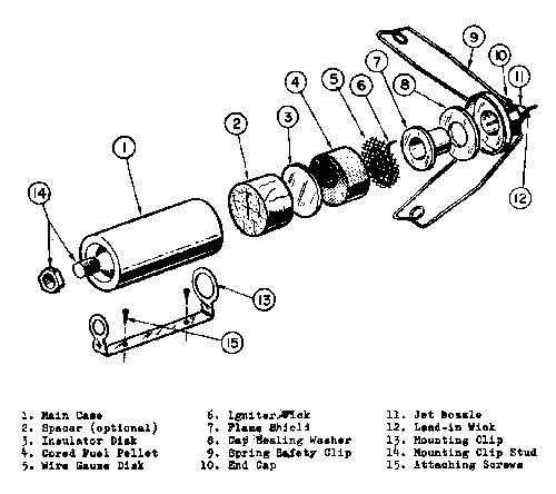
the 50-HT engine, study Figure I to become
fam-iliar with all the parts. Open the engine
by unseating the two spring safety clips (9).
This may be done conveniently by using the
small Jetex screwdriver as a lever [a few of
the early 50-HT engines came with a cute
yellow-plastic handle screwdriver, marked
“Jetex” in red]. Then make sure
that the mounting clip stud (14) and its lock
nut are pulled up tight, as these parts form
the seal at the front end of the main case
(1). Examine the nozzle assembly to see that
the flame shield (7) and the cap sealing washer
(8) are firmly and evenly seated in the end cap
(10). Finally examine the jet nozzle (11) and
if necessary ream it out with the wire paper
clip provided, to remove any machining burrs
[careful here; DO NOT enlarge the nozzle
hole!]. The engine is now ready to be loaded
and operated. (Note that certain replacement
parts such as the spacer insulator disks, wire
gauze disk and cap sealing washer are included
in the 50-HT Fuel and wick
package.)
2. Insert the fuel
charge according to the desired loading
pattern. See Figures 1, 2, and
3.
3. Take about 3" [8
cm] of igniter wick and insert the doubled end
into the fuel pellets an
illustrated.
4. Press the wire
gauze disk firmly in place, with the wick
passing through the edge notch provided for
it.
5. Coil the reminder
of the wick on top of the wire gauze
disk.
6. Place the end cap
on the main case, seating it firmly and even;
then close the spring safety clips. The
screwdriver may be inserted into the loops In
the springs and used as a lever to help do
this.
7. Now snap the
loaded engine into the mounting clip, with the
jet nozzle to the rear of the
model.
8. When ready for
firing, take another 1" [2.5 cm] of igniter
wick and in-sert it into the jet nozzle so that
the inner end will contact the inside coil of
the wick. Not more than 1/2" [13 mm] should
protrude for lighting.
FIRING THE
ENGINE
1. Be sure that the
engine is held securely in the mounting
clip.
2. Push the lead-in
wick in so that it surely contacts the inner
coil of wick.
3. Light the wick,
using a match or any glowing
igniter.
4. Hand launching
should be delayed about two or three seconds,
or until the fuel charge is burning strongly.
A little practice will be helpful in
determining the precise timing at this point.
In static launching, as from a ramp or pad,
support should be provided for at least double
the total length of the
model.
5. In multi-engine
booster operation, restrain the takeoff until
both engines are producing
thrust.
ENGINE CARE AND
MAINTENANCE
1. After firing, one
minute or more should be allowed for the engine
to cool before handling
it.
2. Open the engine as
soon as it is cool and clean all loose ash from
the case, using a wooden stick or dull knife
blade.
3. Clean out the jet
nozzle with the straight end of a paper clip
[gently and carefully!], and scrape all loose
ash from the cap and nozzle
assembly.
4. Examine the wire
gauze disk. If it is not burned out, it may be
put aside for reuse. This part should be
replaced whenever it become so burned or
brittle that it ill no longer fit firmly into
the main case.
5. If the cap sealing
washer is in good condition, the engine is now
ready for reuse. This part should be replaced
whenever it becomes soft or fuzzy, or when
there are signs of power leakage between the
cap and the main case.
6. It is not
necessary to clean the inside of the engine to
a completely bright surface after use. So long
as the fuel pellets fit smoothly into the case,
sufficient cleaning has been done. The LOOSE
ash, however, should never be left in the
engine overnight; it may absorb moisture and
result in destructive
corrosion. |

