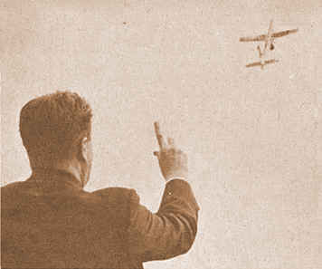
Paul Del
Gatto, the eminent Jetex designer pictured above, shared his thoughts on modelling with
Jetex in his book All about Jetex (publ. American Telasco, undated):
To retain model
proportions, stick to aspect ratios of 4:1 or
under for the horizontal
surfaces.
To eliminate
dihedral, remember to use at least 40°
sweepback, at least on the main horizontal
stabilizing surface. Less than this amount may
prove critical. Use of some sweep- back on the
smaller horizontal surface is also advisable,
though it need not be as
much.
As for the angular
settings of the horizontal stabilizing
surfaces, we would recommend that all rear
surfaces be set at 0 percent, and all forward
surfaces be set at from 1 degree to 2 degrees;
at least until primary flight tests have been
made.
It should be
remembered that these proportions are governed
by the use of flat sheet surfaces. Should we
desire to camber the surfaces or build-up to a
streamlined or airfoiled cross-section, our
minimum critical surface requirements would
vary from 10% less on a model with Jetex 50
engine to 25% less on a Scorpion 600 powered
model.
The establishment of
the proportions of surface to use, related to
the model's weight, has indirectly established
our requirements for a stable flight pattern.
The remaining considerations for stability
depend chiefly on the position of center of
gravity and the location of the engine with
respect to it. As we shall soon see,
variations in the center of gravity position
will assist us in controlling the type of
flight pattern we want.
The ideal position of
the engine as we have been able to determine,
is just forward of the center of gravity
position. Through considerable flight testing
we have found that the most desirable position
of the center of gravity for a conventional
configuration should be approximately 40%--45%
of its total length, behind the nose of the
model. If the proportions of surface are
reversed, so that the larger horizontal
stabilizer is in the rear (Canard), then the
center of gravity will move rearward
approximately to midpoint or slightly
aft.
Moving the center or
gravity rearward, whether by moving the engine
back (preferred) or by adding ballast to the
tail, may result in a slight decrease in the
rate of descent; but at the same time it must
be remembered that this might introduce a
pitching moment (stall) in the climb, and in
the descent pattern. With the introduction of
turn in either direction, through the use of a
vertical trim tab, this condition can be
adjusted.
Powered flight should
be arranged to obtain a straight, or nearly
straight, climb. Setting the center of gravity
(point of balance) of the Jetex unit (loaded)
slightly forward of the model's balance point
will assist in keeping the nose down under
power.
In other words, a
model should be trimmed for a slightly "nose
heavy" condition until the charge bums away.
To maintain a Jetex in a straight climb, it is
best to offset the motor the side, twisting it
with relation to the model's centerline, and
compensating this by offsetting the rudder
until this side thrust is
neutralized.
Due to the motor's
proximity to the center of gravity, very little
side, or down, thrust can be achieved by
swivelling the motor unless angles of about 10
degrees applied. Positioning the motor to one
side of the model often proves more
effective.
For contest flying,
where it is necessary to get the utmost out of
a model, a smaller and more powerful ship in
necessary. Light weight is an important factor
too. The smaller and lighter a model is, the
faster will be the rate of climb--and the more
critical it will be to adjust. Naturally, it
is necessary to take chances to get the highest
possible altitude.
The limit on minimum
size than becomes the amount of wing area
required to produce a good and soaring glide
path, plus maintaining a design that is capable
of stability under excess
power.
Regarding
longitudinal stability, a good contest layout
is often similar to an all-balsa hand-launch
glider where the ship in trimmed with a minimum
amount of longitudinal dihedral--the wing and
tail being set as close as possible to
zero-zero with relation to each other. This
setting minimizes the possible chances in
longitudinal stability between high-powered and
slow-gliding flight. Obviously this means
trimming with the center of gravity well aft,
near the trailing edge of the wing, and reduces
the “static margin" or inherent stability
of the ship. Careful and patient flight
adjustment is, therefore, essential for
ultimate success.
“Flying
Wing” designs are particularly suited to
Jetex power. Models of this type, usually
sensitive to torque, can be trimmed with
relative ease if they are built large enough to
handle the power. Note that the overall drag
is considerably reduced, which means that the
models should be built at least twice the size,
in wing area, as conventional wing and tell
ships. Longitudinal stability on wings is
achieved through the use of “up-down"
elevons or flaps making them sensitive to
longitudinal trim because of the high/low speed
pattern.
A small highspeed
ship, therefore, will require a thrust line
mounted fairly high above the wing and the
exact amount can only be found by trial and
error tests. This again emphasizes the need to
build ships very large until the stability
problem is resolved.
The high
thrust/shorter duration Jetex 50-HT requires
special considerations. To handle the higher
thrust of this engine, longer moment arms and
higher thrust lines must be employed (just as
with freeflight gas models). Wing sections
must be thinner, and double-surfaced wings are
common. Structures must be generally
sturdier.
|