|
|
|
|||
|
|
||||
|
|
||||
| Plan: Zephyr | ||||
|
|
HOME | SITE MAP | FORUM | CONTACT |
|
||
|
ABOUT | MOTORS | MODELS | ARCHIVE | HISTORY | STORE | FAQ | LINKS
|
|
|
|
|||
|
Zephyr
View or download plan for Zephyr Reprinted from Aeromodeller, June 1948, pp. 354-356 |
||||
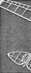
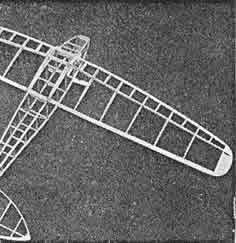
Mainplane. This is in three sections, right, left and centre section, cemented together and reinforced at the joints by a hard balsa bridge piece cemented to the rear face of the main spar, and a 20 gauge steel wire strip cemented and bound with tissue to the front face of the trailing edge. Tailplane. Build the tailplane on the drawing, as the leading edge if of 1/8th and- the trailing edge of 1/16th balsa, place strips of 1/32 sheet balsa between the drawing and the under- side of the trailing edge to raise it to the correct position. |
|
-
Aeromodeller, June 1948, p. 355
|
||
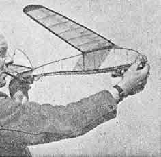
Flying. Trim the model for gliding with the Jetex unit unloaded. The extra weight of the loaded unit and slight down thrust counteracts the tendency to climb too steeply under power. Fine adjustment of downthrust can be obtained by placing thin washers between the Jetex base and the under- side of the fuselage. |
|
-
Aeromodeller, June 1948, p. 355
|
||
|
|
|
|||
|
|
|
|
|
|
|
|
Acknowledgements Article source: - "Zephyr": Bill Henderson |
|
|
|
|
ABOUT | MOTORS | MODELS | ARCHIVE | HISTORY | STORE | FAQ | LINKS |
|
|
Terms of Use
|
Queries? Corrections? Additions?
Please
contact us.
|
|