 |
 |
|
|
 |
Reprinted from Model Aircraft, February 1951 (pp. 65-66)
|
|
|
It is not often appreciated that the major problem facing designers of any type of rocket motor is dealing with the very great heat required to generate gas at sufficient pressures to work it.
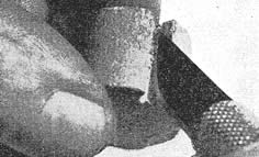
The fuel used on “Jetex” motors generates a gas with about 5 per cent solid deposit and about 30 per cent steam. You have, therefore, three major problems to deal with – heat, deposit and steam, and as these all directly affect the maintenance of your motors, it is as well to understand why certain things happen to a “Jetex” motor after continual use. In the first place, the rubber impregnated asbestos washers which are made of a very high quality material and on the whole stand up to the job remarkably well, undergo disintegration of the rubber after the first firing, and the rubber sometimes welds itself to any metal surface which it contacts. There is, therefore, a tendency, after the first firing, for this washer to tear, due to the surfaces being welded to the wrong surface. It obviously does not matter if the washer welds itself to the cap, but if it does so to the annular groove in the main case, the washer may have a slight pit where the graphited rubber surface has been torn off. It does not follow, however, that the washer necessarily need be replaced, but after the first firing, it is always as well to bed the washer in by carefully removing any parts sticking to the main case, and revolving the cap under pressure so that the surface of the washer is honed smooth. This, I think, deals with the main trouble caused through heat, but it should be borne in mind, that if once a pit starts in the washer and the smallest gas leak occurs in its surface, the hot gases will drill a channel through this and eventually damage the main case, as there is a great concentration of heat on one part of the metal which gradually burns away and collapses with the internal pressure of the motor [see illustration right].
|
|
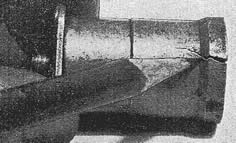
A badly pitted cap washer will cause a gas leak and can result in the main case cracking
|
We now come to the problem of solid deposit. In some ways, this is an advantage as it tends to seal any small pits which might cause gas leaks after the first firing. It also acts as a most convenient heat insulator between the metal sides of the case and the hot burning charge, and it is no advantage to scrape too much of this deposit away, although it will eventually build up a wall of such thickness that it becomes difficult to insert the pellet [see illustration right]. When this happens the deposit can easily be softened with water and it will probably be found necessary to clean some off after every 20 flights.
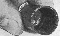
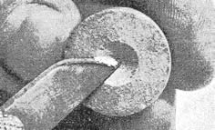
Having dealt with the main case of the motor, the cap is unfortunately a different proposition, as this deposit has a strong tendency to find its way into the threads of the screw type jets in all “Jetex” motors except the 50. It also builds up into a hard black cake round the entry to the jet itself, and after a time this appears to have a chemical action on the metal from which the jet is made, and pits and grooves are gradually eaten into it. This, of course, does not happen immediately and time is the major factor rather than continual use. If you are to have a long life from your “Jetex” motor, you should remove the jet after every few flights, wash it in water, scrubbing away any deposit that has settled on it and oil it to prevent rust, before replacing [see illustration right]. This is especially necessary if you are likely to put your motor aside for several weeks after having used it, and I cannot emphasise too strongly the necessity for thoroughly inhibiting, (i.e. cleaning, taking to pieces and preserving) if this is likely to happen. Chemical action continues whether a thing is being used or not.
The third factor is steam, and this obviously will tend to cause the oxidisation of the metal used in the jets, which should be well scrubbed and cleaned (a pipe cleaner is a very useful tool), and then inhibited in oil as I previously suggested. Too much oil will probably cause a slight carbonisation, and before use, any excess oil should be wiped clear.
|
|
The solid deposit which forms on the inside of the case makes an insulator between the burning charge and the case. Only sufficient of the deposit should be removed to permit easy insertion of the fuel pellet
The jet orifice in the cap must be cleaned frequently, particularly the cone shaped jet entry. The cap shown on the right has become badly corroded, making it impossible to unscrew the jet for replacement or cleaning
|
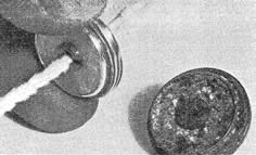
Where two or more pellets are used in “Jetex” motors, it has been found that the last pellet burns at a slightly higher rate than the first. This is caused through the motor being generally warmed up, and it works at a higher internal pressure, thus giving more efficiency. Some of the wise boys will deliberately allow the first pellet to burn away before launching their model in contest flying, and this is obviously an advantage where ratio judgment is being given, as the loss of motor time is amply compensated by the extra urge on the last few seconds of thrust, plus the loss of weight in fuel. There have been several attempts by people anxious to get the most out of their motors, to burn the pellet down the side, and I have actually seen a pellet which has had a groove carefully filed down the side so that the igniter wick would ignite a larger surface of the pellet than the face. This is a highly dangerous practice, and I cannot recommend it [see illustration right]. Uncontrolled burning must obviously take place as the whole conception of the “Jetex” pellet is that it burns steadily down from the face, and that the area of gas-producing material is never exceeded throughout the whole burning time. The manufacturers have spent many months of experimenting with the lightest and strongest motor case available to work at a given pressure, and you are, therefore, liable to damage your case and produce a most erratic thrust curve which will not in the long run, do the flight of your model any good if you adopt practices of this description.
Another point which is, perhaps, worth mentioning, is that the igniter wick itself has a thin copper core. This core is usually melted and blown out through the jet in the first few seconds of ignition, but occasionally a thin length of it remains in the jet orifice. It is easy to pull this away and it is also advisable to do so as it has a tendency to angle the jet stream which would produce a certain amount of side thrust where it is not wanted.
|
|
A practice which is not recommended. Some modellers cut a groove in the side of the charge to obtain a larger burning surface. The result is uneven burning and an erratic thrust curve
|
The average “Jetex” motor gives a very constant power curve, but the final question which I have been occasionally asked, is how to smooth this curve out where more than one pellet is used. In the 350 pellets, the base of one side is dished, and if the instructions are carefully followed and a little loose powder is scraped off the top of the bottom charge, a rapid take-over can be effected. In the case of the “200” motor, however, the cone or dish in the bottom of the pellet has to be cut in by the user himself [see illustration right]. It is, however, the most effective means of keeping the power curve constant, and the practice of using a small piece of igniter wick sandwiched between two pellets is not altogether a good one as it has a tendency to give a minor explosion which does not necessarily mean rapid ignition of the bottom charge, but in most cases lifts the whole end cap for a split second and releases pressure with a resultant loss of thrust.
|
|
Even burning can be assisted by cutting a cone in one end of the pellet, the end with the cone being placed against the flat base of the second charge which will become more readily ignited
|
|
|
|
|
 |