 |
 |
|
 |
  |
Reprinted from Aeromodeller, September 1953, pp. 536ff.
THE Jetex model
appears basically very simple,
with a self-contained constant-thrust power unit
which requires no adjustment and the minimum
of servicing. About the only "maintenance"
required, in fact, is periodic cleaning of the Jetex
motor, and even this very necessary feature is
often ignored with not too harmful results.
What is not commonly realised, however, is that
trimming a Jetex model almost exactly reverses
the trimming process associated with a rubber
model. In the latter case we start with low turns
and progressively work up to maximum power,
adjusting trim at each intermediate stage, as
necessary. With a Jetex motor, ignoring the initial
period when the charge is developing its full
burning rate, the thrust from the motor is
appreciably constant, but the efficiency increases
over an appreciable part, if not the whole, of the
power run. This means that it is the end part of
the power run with a Jetex motor which can be
critical as regards trim, not the initial few seconds
as with a rubber model.
|
|
 |
Fig. 1
|
A simple explanation
of why this should be so
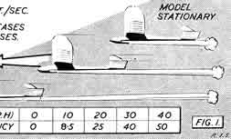
can be given. A measure of the efficiency of the
jet unit is given by dividing the flight speed by the
jet velocity of the unit. With a standard Jetex
the exhaust velocity, or the speed at which the
burning gases escape from the nozzle are of the
order of 1,000 feet per second or more. If
stationary, then the efficiency of the jet unit is
zero, since it is doing no work. As the model speeds
up the "efficiency ratio" increases. At just over
10 m.p.h., for example, it is 1/120, increasing to
1/40 at a little over 20 m.p.h., and so on—Fig. 1.
With a given thrust output the model will, in fact,
tend to speed up until the drag generated exactly
balances the thrust, in purely horizontal flight.
|
- Aeromodeller, September 1953
|
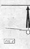 |
Fig. 2
|
This does not necessarily mean that "normal" duration dihedral angles are necessary with Jetex models. If, for considerations of scale or semi-scale appearance, we want to use small dihedral angles a certain corresponding fin area can be found to give optimum spiral stability for that particular combination. Unfortunately there are no simple rules as to how this fin area (and shape) can be determined. At best the result can only be a "guesstimation", adjusted by trial and error methods as necessary. Even if the resulting combination has not got all the spiral stability we want, we can still fly it successfully with Jetex power, simply by trimming the power flight so that the model does not adopt a severe angle of bank which will lead to loss of lift, the model speeding up and aggravating the stability problem—Fig. 2. In other words, the model is trimmed to fly appreciably straight under power, when trimming is concerned mainly with making sure that it does not go over into a loop as the efficiency of the motor increases with increasing model speed. As a general rule it pays to fly all types of Jetex models appreciably straight, or in wide circles, under power. To do this consistently demands a structure which is rigid enough to maintain its setting and remain free from warps. The effect of small warps may not show up at low speeds (such as hand glide tests) but may well upset our ideas on straight trimming under power.
|
- Aeromodeller, September 1953
|
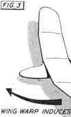 |
Fig. 3
|
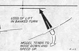
It does not follow, for example, that corrective action taken to offset the effect of a warp at one speed will remain "in balance" at other speeds. In the case of a wing warp corrected by rudder offset to give a straight glide from a hand launch, the relative power of the two turning forces generated may diverge considerably as speed increases when- Jetex thrust. is applied—Fig. 3. The model then turns one way or the other, depending on which over-rides the other—the warp or the "corrective" rudder. Such divergencies will show up more markedly towards the end of the power run.
There is, of course, another way in which this bugbear of Jetex trimming can be tackled—proportion the model so that the drag increase with increasing speed under power soon reaches a balancing figure. In other words, the model is virtually underpowered, as compared with normal design practice for the size of Jetex motor considered. This is not good practice where optimum performance is required for, by limiting the flight speed, we are also operating the Jetex at lower efficiency. But it is a safer way of flying. The opposite also holds true in that a model trimmed quite satisfactorily with a particular Jetex motor may become unstable towards the end of the power run if a more powerful fuel is used in that same motor. Obviously for duration flying we want as much power as possible from the Jetex motor and so the use of a more powerful fuel is attractive from this point of view. Before the introduction of "Red Spot" fuel, in fact, it was quite common practice to cut down "350" size fuel pellets to it "200" or "100" motors, since these were found to provide more thrust than standard fuel charges for the smaller sizes of motors. Wasteful, perhaps, but considered worth it in the interests of maximum performance.
|
- Aeromodeller, September 1953
|
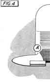 |
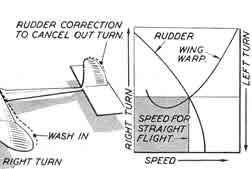
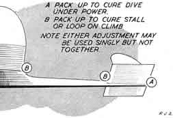
Fig. 4
|
Theoretically, the faster the Jetex model flies under power the better from the point of view of sheer efficiency (i.e., getting the most out of the power run) which means, in effect, a minimum size model for duration work. The real limit then becomes the amount of wing area required to produce a low wing loading for optimum glide performance, coupled with the necessary tailplane area and design layout to ensure stability under power. The smaller the model and the faster it Hi under power, the more tricky it may prove to Actually, trimming a typical Jetex model if not as difficult as it may appear from the above descriptions, provided the design layout itself is basically sound. For sports flying all that is really necessary is a substantially straight power-on flight or a wide sweeping circle, when the necessary longitudinal control to prevent the model either diving or nosing up into a loop or stall as speed builds up can be achieved by adjusting the incidence of the tailplane a small amount at a time. Packing strips used for tail trimming in this manner should be 1/64 balsa or pieces torn off a cigarette packet (just over 1/100 of an inch thick on average), not thicker, adding or taking away one piece at a time. The resulting glide may not be as good as it could be, but this can be ignored where maximum duration is not the aim—Fig. 4. Once the correct packing has been found it should be cemented in permanently.
Trimming for duration, a good glide trim is just as important as the power trim. The power run represents only a fraction of the total duration required—say a tenth or less—and to have the model slightly out of trim for nine-tenths of its flight in the interest of getting the first one-tenth right is bad practice.
|
- Aeromodeller, September 1953
|
 |
Fig. 5
|
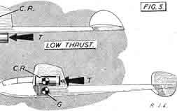
Successful Jetex duration models have had the power unit mounted both above and below the wings—Fig 5. In the former case the line of thrust is usually substantially below the centre of resistance of the whole model, and below the centre of gravity, so that power-on flight does tend to nose the model up. Generally such models are more prone to loop than those with the thrust line appreciably level with the centre of resistance, as in the second layout. In the main, however, a slight nose-up tendency would appear to be more desirable than a "balanced" or nose-down power-on trim. A loop can, by careful trimming, be turned into a spiral climb. Spiral dives are usually initiated by the model nosing down as it circles, and a spiral climb can just as easily turn into a spiral dive if overdone.
|
- Aeromodeller, September 1953
|
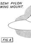 |
Fig. 6
|
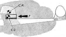
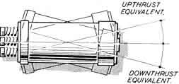
The most satisfactory solution for duration flying seems to be an underslung Jetex unit but mounted reasonably close to the wing, as in Fig. 6. Such a model can usually be trimmed out satisfactorily with a wide sweeping climb. Provision for adjusting the position of the thrust line in a vertical direction (up or down) whilst still remaining substantially horizontal would also be a good thing. The effect of offsetting the Jetex thrust line (i.e., equivalent to sidethrust or down or upthrust) is usually insignificant unless appreciable angles of offset are employed. Some Jetex experts do use an offset thrust line to achieve optimum trim under power, consistent with the best glide trim; others appear to get similar results with the thrust line substantially parallel to the fuselage. See Fig. 7.
|
- Aeromodeller, September 1953
|
 |
Fig. 7
|
Some of the little "tricks of the trade" employed in duration contest work take advantage of the fact that a "hot" Jetex motor generates more thrust than a "cold" one. In other words, with multi-charge units (e.g., Jetex 200 and 350), the second (or final) charge generates more thrust than the first. For "ratio" contests (and most Jetex contests are based on flight ratios), single- charge only is used, as a general rule. But a multi-charge unit is loaded with full charges and ignited in the normal way. The model is then held until the first charge has burnt out and only launched when the second charge has fired.
The increased thrust effect of the second charge is most noticeable if a normal flight is made with two charges. The model drops into a glide when the first charge burns out, and then picks up again into a climb as the second charge cuts in. The climb on the second charge will be appreciably better in most cases, provided the model is trimmed out satisfactorily.
The standard rating for length of power run with different Jetex combinations is given in the table. These are the figures usually adopted for contest work, but very slightly in practice with individual charges and the condition of the Jetex unit Notching the edges of the charge or cutting away for a loose fit generally tends to build up more gas pressure, increase the thrust and lessen the length of power run. Partially clogged jets may increase the power run and decrease the thrust produced. The size of the jet hole in the Jetex unit is critical, for optimum performance, emphasising the necessity for careful, regular cleaning.
In fact the maker's instructions should always be followed for best results. Their recommendations on cleaning and loading, etc., are based on more experience than any individual flyer is likely to amass.
|
- Aeromodeller, September 1953
|
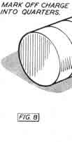 |
Fig. 8
|
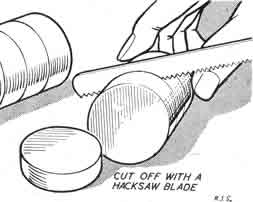
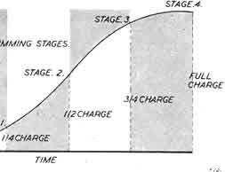
Trimming for duration can be attempted on a "progressive" basis by using cut-down charges for reduced power-on duration. An old hacksaw blade is a useful tool for slicing up individual charges—Fig. 8. With a number of quarter charges, however, we can tackle the business of approaching the "critical speed" in stages without the possibility of winding up the first power-on test flight (with a full charge) in disaster. The "critical speed", of course, is the maximum speed which the model will reach on a full charge, which will vary with individual designs. Fig. 9 shows, diagrammatically, how this can be approached in stages with cut-down charges, trimming out at each stage, as necessary.
|
- Aeromodeller, September 1953
|
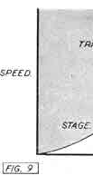 |
Fig. 9
|
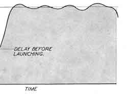
In practice the use of a single quarter charge is often of dubious value. The thrust of a Jetex motor builds up relatively slowly at first and all Jetex models need to be held in the hand until the full thrust builds up before launching. The remaining power-on duration with a quarter charge is then a matter of two or three seconds at the most-rather too short for comfort since it may cut and leave the model in a stalled attitude with too little altitude for recovery. Usual practice would call for initial flights with a half charge. An alternative method, of course, is to load with a full charge each time and delay the launch to "time" the power run, in stages. This is more wasteful of charges, but rather more accurate in the long run.
|
- Aeromodeller, September 1953
|
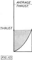 |
Fig. 10
|
Finally, we would like to explain how the power rating of a simple jet engine, where performance is expressed in terms of thrust developed, can be compared with performance of propeller driven aircraft where the engine horse power is specified. With a constant thrust jet engine, the equivalent horse power of that engine is simply related to the product of the speed at which it flies the model and the thrust it is developing. In other words, horse power equivalent is a combination of the speed/time and thrust/time curves of Figs. 9 and 10. In a simple formula :-
| |
|
T.V. |
| H P.
(Jetex) |
= |
|
| |
8,800 |
| where
T |
= |
thrust in ounces |
| V |
= |
velocity in ft./sec. |
Thus a Jetex 100 developing thrust of 1-2 ounces producing a critical or maximum speed of 20 m.p.h.
with any particular model is developing a maximum of .004 horse power. Horse power rating ranges
from zero at the start of the flight (no forward speed) to a maximum at this critical speed,
intervening values depending on the form of the speed/time curve for that particular model.
|
- Aeromodeller, September 1953
|
|
|
 |