|
|
|
|||
|
|
||||
|
|
||||
| The The (Jet)X Files | ||||
|
|
HOME | SITE MAP | FORUM | CONTACT |
|
||
|
ABOUT | MOTORS | MODELS | ARCHIVE | HISTORY | STORE | FAQ | LINKS
|
|
|
|
|
|
||||||||||||||||||||||||||||||||||||||||||||
|
The (Jet)X Files 2
for February 2003
by Roger Simmonds Reprinted from SAM 35 Speaks, February 2003 (with revisions) Though I am something of a late comer to the present small jet plane scene, and no expert in the Jetex field, I nevertheless do like to share my enthusiasm for these models. I am particularly interested in classic Jetex designs and their adaptation for Rapier power or even (heresy!) miniature electric ducted fan. I love many of the new models too, especially if they are "traditional builds". In this column I hope to celebrate past achievements and report developments in the field as they relate to SAM activities. Now I know there is a lot of good information, old and new, "out there" in the various "Jetex" related websites, including a "History of Jetex", many plans for free flight duration models, new formulations of Jetex compatible fuel, and alternatives to Rapiers. However, not everyone has access to the Web, or enjoys ploughing through the mire if they have. A website is different from a column in a printed magazine, but I hope there is a place for both in the Modern World. If I can sift out some relevant information and help inspire someone to fly jets and make proper planes I will be overjoyed. I would love any feedback, corrections etc. more knowledgeable readers care to give. |
|
||||||||||||||||||||||||||||||||||||||||||||
|
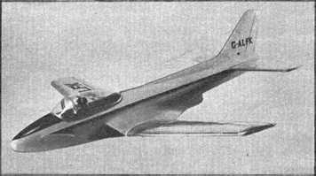
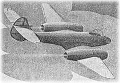
The previous article made some rude remarks about externally mounted motors in troughs. I was not sure whether the smaller size augmenter tube was compatible with either the Rapier L2 HP (more than equivalent to a Jetex 50) or L2 (with a thrust somewhere between an Atom 35 and the original 50). Some of the old designs, if they are to be Rapier powered, would need modification to incorporate a tube of different shape, possibly made of titanium! If one eschews the trough, though, and doesn't want the complication of an augmenter tube, is there an alternative approach to hiding the motor? In semi scale designs such as the Sebel Lynx (right), and early jet marques like the Yak 9 the motor can be put in a "jet pod" under or just in front of the wing. Tailless designs such as the Yak 25 or Cutlass might accommodate motors in the rear fuselage, but there is a very limited choice of prototypes which this compatible with a motor in a sensible position. Motors can be contained in the engine nacelles, but putting Jetex units out on the wings is not a good idea as this arrangement can present difficulties in achieving a stable, or indeed any, flight pattern. The Aeromodeller Meteor IV (right) for two 100s (1948) was notoriously difficult to fly. The design may be more viable with Rapiers, which really are more suitable than Jetex for twins, being easier to start and the propellant is less sensitive to changes in temperature and pressure. Power is reproducible and, since there are no pellets, thrust (though it may build up) is not as variable during flight. However, there were many nice early designs where there are two turbo jets in the fuselage, (the Scimitar for example) or a single turbo jet pipe is bifurcated and exhausts are close to the fuselage side (such as a the shapely Hawker P.1052). This reduces possible asymmetric thrust, and twin Jetex power for such prototypes makes more sense, though another problem may then arise.  |
|
-
Royal Air Force Flying Review, Vol. XVI, No. 2
-
Aeromodeller, June 1948 (p. 355)
 |
|||||||||||||||||||||||||||||||||||||||||||
|
A classic design of the Fifties was the Wilmot Mansour Saunders Roe (SARO) A/1 flying boat. This was, to say the least, an interesting and unusual prototype designed by A.A. Judge for two Jetex 50s. It is quite sizeable, with a span of 20", a length of 18.5" and a weight of about 65g. The construction, as can be seen from the plan [above], is quite complex, though characteristically elegant. The model has two very interesting features. First, there is a pendulum operated auto rudder, a tacit admission of the difficulties of operating two even closely spaced Jetex motors (I wonder if it was effective). Secondly, the motors are placed in a scale position behind CG, angled so as to give several degrees of upthrust. |
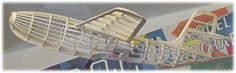 Jetex SARO A/1, Southhampton Hall of Aviation
- Howard Metcalfe
|
||||||||||||||||||||||||||||||||||||||||||||
|
Now, for good reason, most models have the motor at or in front of the CG, with a thrust line parallel to the wings. Following the example of Bill Dean's archetypal MIG 15, many modern designs have a wing set at zero degrees to the fuselage and the tail plane at minus two degrees. With such a set up, trimming, in the main, (and to simplify) consists of moving the CG (usually forward) to achieve a fast straight glide. Get this right (even at the expense of the CG apparently being at an absurd position such as in front of the wing leading edge for some straight wing designs), and a safe powered flight pattern is practically assured. It was not always thought so, I believe, in the old days. The guidelines followed (see for example SAM 35 Speaks, August 1993) seemed to be to trim for a "floaty" glide and then apply "down thrust" to kill the power stall. Now there does appear to be a problem with this. I cannot see how, with the motor around the CG, any change in the thrust line of less than say thirty degrees can have had any effect on the flight pattern. I have read that Phil Smith recommended "cigarette paper under the front of the Jetex mount", so it appears very subtle changes were being aimed at. I have looked hard at the "triangle of forces" and "downthrust" just doesn't make sense to me. Can anybody enlighten me as too what was going on here? |
|
||||||||||||||||||||||||||||||||||||||||||||
|
It is accepted wisdom that at best there should be no significant shift of CG in flight, especially rearwards. The SARO A/1 motors are some 4" behind the CG, which inevitably would have moved back as the fuel burned. The motors are set at a significant negative angle to the centre line, and emphasis was placed in the instructions on carefully aligning both Jetex orifices. Getting the angle of thrust "right" and symmetrical was obviously thought to be critical to flight performance. The instructions also say that the glide with empty motors should be "straight and flat with a slight tendency to nose heaviness". One can see that such a set up could work, just. The thrust line is through the vertical CG; as the fuel burns the CG moves forward for a swift glide to earth. OK, and according to Mike Ingram of Wilmot Mansour this actually did work in practice, which is somewhat surprising, given the possible inconsistency of power output. If this arrangement was viable, then other designs such as the P.1052 are a candidate for a similar set up. On reflection, I think the SARO A/1, with its possibly "knife edge" trimming and complicated structure is for experts only! Still, it is a most fascinating design, and really quite tempting. The model is suitable for two L2 HPs, or two L2s if built light, but it might be better to reduce the plan by 40% to give a span of around 12", simplify the structure, and fit L1s. The model would be a lot lighter, less prone to damage in testing, and will also cheaper to trim! The A/1 is a good example where a trough just wouldn't be right. It wouldn't ROW for a start! However, a trough is such a natural and effective solution to the "where to put the motor" problem that its universal application, even to twin engined designs such as the Skyleada Canberra (1953), was perhaps all but inevitable. It could be argued that in flight these non-scale features don't show anyway. To their great credit Wilmot Mansour and their designers thought differently, and produced commercial models that can still inspire and challenge us today. |
-
Aeromodeller, June 1953 (p. 321)
|
||||||||||||||||||||||||||||||||||||||||||||
|
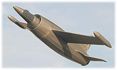
I hope to assay a model that can accommodate a Rapier L2 in a balsa and aluminium foil pipe of large (1.25") diameter. The airflow will cool the pipe, and all the smoke (hopefully only from the motor, and not the burning model) will exit via the jet pipe. A certain early French prototype of similar proportions to the Aerographics Bell XS-1 has a ramjet of the necessary size, so plans are being drawn up. A further consideration is that with the proposed configuration a deflector plate in the pipe could always be used to apply down thrust. A Leduc 021 with a floaty glide in a thermal? Now that really is a thought. |
-
Roger Simmonds
|
||||||||||||||||||||||||||||||||||||||||||||
|
|
|
||||||||||||||||||||||||||||||||||||||||||||
|
|
|
|
|
|
|
|
Acknowledgements - Article and illustrations (Lynx, Jetex SARO A/1 plan, Leduc 021) contributed by Roger Simmonds - Illustrations (Gloster Meteor, SARO A/1 advertisement) contributed by Bill Henderson - Illustration (SARO A/1 model) contributed by Howard Metcalfe |
|
|
|
|
ABOUT | MOTORS | MODELS | ARCHIVE | HISTORY | STORE | FAQ | LINKS |
|
|
Terms of Use
|
Queries? Corrections? Additions?
Please
contact us.
|
|