|
|
|
|||
|
|
||||
|
|
||||
| ARCHIVE: Patent 712,551 | ||||
|
|
HOME | SITE MAP | FORUM | CONTACT |
|
||
|
ABOUT | MOTORS | MODELS | ARCHIVE | HISTORY | STORE | FAQ | LINKS
|
|
|
|
|
|
|||
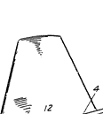
The preferred construction according to the invention will now be described by way of example with reference to the accompanying drawings, in which:-
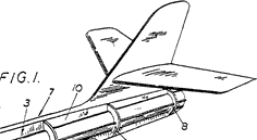
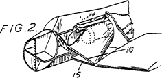
Figure 1 is a perspective view of one model aircraft with some parts broken away; Figure 2 is similar to part of Figure 1, but with different parts broken away; Figure 3 is an elevation, partly in section, |
|
 |
||
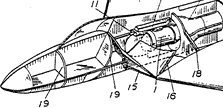
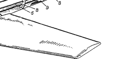
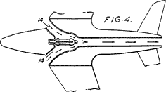
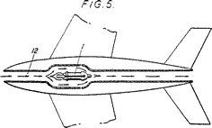
Figure 4 diagrammatically shows the air and gas flow through the aircraft; and Figure 5 is a diagram, similar to Figure 4, showing the flow through another aircraft. The aircraft show [sic] in Figure 1 is a model of a jet fighter and is powered by a small reaction motor 1 which contains a gas-generating charge and has a rearwardly directed jet member 2 formed with a jet orifice as usual. The motor lies in the central part of the aircraft and the centre of gravity of the aircraft lies between the ends of the motor. The gas-discharge end of the motor, including the orifice member 2, is surrounded by the front end of a sheet metal augmenter tube 3 which has a bell-shaped mouth 4 which fits telescopically into the main part 5 of the tube. This part 5 extends to the tail end of the aircraft. The tube 3 has side flanges 6. The fuselage, indicated generally at 7, is built up from two longitudinal shells assembled around the augmenter tube 3. Each shell comprises bulkhead parts 8 shaped to fit closely around the part 5 of the augmenter tube 3, a bulkhead part 18 shaped to fit closely around the mouth 4 of the: tube, and forward bulkhead parts 19. The parts 8 and 18 are slotted to receive the side flanges 6 of the augmenter tube 3. Each shell also comprises a balsa wood skin 9 bonded to the outer edges of the bulkhead parts 8 and a longitudinal wall 10 to which the inner edges of the bulkhead parts 8 are bonded. Each wall 10 lies on the centre line of the aircraft and is made with a central longitudinal opening to accommodate the motor 1 and augmenter tube 3. The two shells are assembled around the motor and augmenter tube, and the two walls 10 are then bonded together face of face. Thus the augmenter tube is wholly enclosed in the tail part of the aircraft and forms the main structural member of the tail part of the fuselage. |
|
|
||
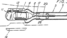
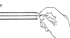
There are two air intake ducts 14, one at the root of each wing, as diagrammatically illustrated in Figure 4. Each of these is bounded partly by the lower surface 15 of the wing and partly by a fairing 16 which runs to the bulkhead part 18 around the mouth 4 of the augmenter tube 3. The propellant charge in the motor is ignited by a wick 17 as described in our Specification No. 642,689. This wick projects rearwardly from the motor into the mouth 4 of the augmenter tube 3, and to ignite it a wire 25 bent spirally into a coil 26 at its forward end may be pushed up the augmenter tube, the coil carrying a fuze 20 which is lit before being inserted into the tube. In operation air is drawn in through the ducts 14 and entrained by the gases from the motor into the tube 3, as shown in Figure 4. In another construction, a single air intake duct extends from the nose of the aircraft to the motor, as diagrammatically shown in Figure 5. If desired, there may be two motors side by side and two corresponding augmenter tubes placed side by side as twin structural members. What we claim is:— 1. A model jet aircraft having a motor containing a solid fuel charge at or close to the centre of gravity of the aircraft, in which an augmenter tube is provided to receive the gases emerging from the jet orifice of the motor and constitutes the main structural member in the tail part of the fuselage. 2. A model aircraft according to Claim 1 in which the tail part of the fuselage comprises a skin fitting over transverse bulkheads which fit closely around the augmenter tube. 3. A model aircraft according to Claim 1 or Claim 2 in which the front end of the augmenter tube is aligned with an air intake duct lying around the forward end of the motor and extending forwards either to the nose of the aircraft or through two branches to the front junctions of the wings and the fuselage.
For the Applicants:
GILL, JENNINGS & EVERY, Chartered Patent Agents, 51/52 Chancery Lane, London, W.C.2. Abingdon: Printed for Her Majesty's Stationery Office, by Burgess & Son (Abingdon), Ltd.—1954. Published at The Patent Office, 25, Southampton Buildings. London, W.C.2, from which copies may be obtained. |
|
|
||
|
|
||||
|
|
|
|||
|
|
|
|
|
|
|
|
Acknowledgements - Original patents located, copied and compiled by Gerhard Everwyn; contributed by Terry Kidd |
|
|
|
|
ABOUT | MOTORS | MODELS | ARCHIVE | HISTORY | STORE | FAQ | LINKS |
|
|
Terms of Use
|
Queries? Corrections? Additions?
Please
contact us.
|
|