 |
 |
 |
 |
 |
|
PATENT SPECIFICATION 642,689
|
|
Date of filing Complete Specification: Oct. 25, 1948.
Application Date: Nov. 11, 1947. No. 30022/47.
Complete Specification Published: Sept. 6, 1950.
PROVISIONAL SPECIFICATION
Improvements relating to Reaction Motors Suitable for the Jet Propulsion of Model Aircraft or the like
We, WILMOT MANSOUR & COMPANY LIMITED, a British Company, of Salisbury Road, Totton, Hampshire, and CHARLES MANDEVILLE WILMOT and JOSEPH NAIME MANSOUR, both British Subjects and both of the Company's address, do hereby declare the nature of this invention to be as follows:—
|
|
|
This invention relates to reaction motors of the rocket-type, that is to
say motors in which the forward thrust is produced by the reaction of the
rearward discharge of gases of combustion. Despite the obvious advantages
of using such a motor in a model or toy aircraft, vehicle or vessel no practical
form of motor small enough for use in such a model or toy has yet been developed.
|
|
Despite the obvious advantages of using such a motor in a model or toy […] no practical form of motor small enough […] has yet been developed.
|
In a motor for this purpose the gases may be generated by igniting a composition inserted in pellet form into a casing, the ignition being effected by producing a temperature of about 200° C. by means either of a fuze or a hot point. In constructing such a motor, lightness of weight is essential and in consequence the strength of the parts is necessarily comparatively low. In particular the casing in which the gas-generating charge is placed and in which it burns must be made as thin-walled as possible. To produce the necessary forward thrust the combustion gases must pass rearwardly through one or more small jet orifices. There is a risk of these becoming clogged and in such a case the gases will be unable to escape and a high pressure will rapidly be developed. This may well lead to bursting of the casing.
|
|
To produce the necessary forward thrust the combustion gases must pass rearwardly through one or more small jet orifices. There is a risk of these becoming clogged […]. This may well lead to bursting of the casing.
|
According to this invention a member containing one or more jet orifices
through which the combustion gases are discharged is made movable relatively
to the casing and is subjected to spring pressure such that it can move
to allow the combustion gases to escape past it if abnormal pressure builds
up in the casing but is held in position while the gases are escaping normally
through the orifice or orifices.
In the preferred forms of motor the casing is cylindrical and a cylindrical
gas-generating charge fits closely inside it. The forward end of the cylinder
is closed and the rearward end is constituted by a cap the diameter of which
is the same as the internal diameter of the casing and which is formed with
a central jet orifice. This cap is the member which is subjected to spring
pressure and if it moves rearwardly under abnormal pressure in the casing
the gases can escape radially between it and the rearward end of the casing.
It is found desirable not to shroud the outlet of the jet orifice in any
way. Accordingly it is preferred to put the spring or springs at the forward
end ef the casing and to provide rods outside of and parallel to the casing
through which the spring pressure is applied. In the preferred construction
the cap has slotted lugs with sockets facing rearwardly, and the rods are
formed with hook-shaped ends which enter these sockets. Alternatively a
groove may be made in the rearward face of the cap to receive the ends of
the rods. At their forward ends the rods pass through bearing lugs on the
forward face of the container and in front of it are each surrounded by
a coiled spring which bears at one end on the bearing lug in question and
at the other end on an abutment secured to the end of the rod. The rearward
end of the casing and the inner or forward surface of the cap are both recessed
to accommodate a cylindrical washer, which may be of asbestos and which
seals the joint between the cap and the casing. Such a cylindrical washer
is forced into tight contact with the joint by the internal pressure developed
when the gas-generating charge burns and so is more satisfactory than any
disc-type washer. The cap preferably has a cylindrical flange which projects into the casing in close contact with the washer.
|
|
|
One important advantage obtained by constructing the motor as just described is that there are no screw threads to be machined and all the parts can be made easily and cheaply. Another advantage is that the end cap serves not only as a safety device and jet orifice, but also as a lid which can readily be removed to enable fresh charges to be put into the casing.
Many modifications may be made. A minor one consists in using only a single L5 spring at the front of the casing, this spring surrounding a spigot which projects forward from the casing and bearing on a disc which surrounds the spigot loosely and to which rods running to the cap are connected. Another modification consists in making the member which contains the jet orifice in the form of a cup with the orifice in its base and with a flange which bears through a washer on an internal flange at the rearward end or mouth of the casing. The cylindrical wall of the cup extends rearwardly and is surrounded by a spring which at one end bears on the flange of the cup and at the other end on an internal flange on a cylindrical member which surrounds the spring and cup and is screwed onto the end of the casing. With such a construction it is necessary to insert the gas-generating charges at the forward end of the casing, and this must therefore be provided witha removable end in the form, for example, of a screw-threaded disc.
In yet another modification the jet orifice is formed in a flanged cap which, while closing the open end of the casing lies in a tubular part which is screwed onto the rearward end of the casing and which serves as a housing for a spring by which the cup is held in position. With such a construction the jet of gases flowing out through the orifice passes along the centre of the spring, with the result that there is some loss in the efficiency of the jet as a producer of forward thrust.
In general the spring or springs should hold the cap or other member in position under pressures up to about 100-150 lbs. per square inch but allow the member to move to let the gases escape past it when the pressure rises to about 175 lbs. per square inch.
The motor will normally be secured in the toy or model by a strap surrounding the casing or by some other appropriate device secured to the casing. However, if desired, the motor may be secured by attaching the member which contains the jet orifice or orifices to the model or toy, and then of course it is the casing which moves under abnormal pressure.
Dated this 11th day of November, 1947.
For the Applicants:
GILL, JENNINGS & EVERY,
Chartered Patent Agents,
51/52 Chancery Lane, London, W.C.2.
COMPLETE SPECIFICATION
Improvements relating to Reaction Motors Suitable for the Jet Propulsion of Model Aircraft or the like
We, WILMOT, MANSOUR & COMPANY LIMITED, a. British Company, of Salisbury Road, Totton, Hampshire, and CHARLES MANDEVILLE WILMOT and Joseph NAIME MANSOUR both British Subjects and both of the Company's address, do hereby declare the nature of this invention and in what manner the same is to be performed, to be particularly described and ascertained in and by the following statement :—
|
|
One important advantage obtained by constructing the motor as just described is that […] all the parts can be made easily and cheaply.
|
 |
 |
 |
 |
 |
Various experiments have been made in recent years with model aircraft driven by reaction motors in which the forward thrust is produced by the reaction of the rearward discharge of gases of combustion. The advantages of using such a motor in a model aircraft, vehicle or vessel are obvious, the principal ones being the absence of any torque reaction in flight and the elimination of the need for winding any rubber-band motor. So far, however, no practical form of motor small enough to be suitable for use in such a model or toy has been developed. The invention is concerned with reaction motors of this small type:
In a motor of the type set forth for use in a model aircraft or the like, the gases 95 may be generated by igniting a composition inserted in pellet form into a casing, the ignition being effected by producing a temperature of about 200° C., by means either of a fuze or a hot point. In constructing such a motor, lightness of weight is essential and in consequence the strength of the parts is necessarily comparatively low. In particular the casing in which the gas-generating charge is placed and in which it burns must be made as thin-walled as possible. To produce the necessary forward thrust the combustion gases must pass rearwardly through one or more small jet orifices. There is a risk of these becoming clogged and in such a case the gases will be unable to escape and a high pressure will rapidly be developed. This may well lead to bursting of the casing.
According to this invention a member containing one or more jet orifices is made movable relatively to the casing for the gas-generating charge and is subjected to spring pressure such that it can move to allow the combustion gases to escape past it if abnormal pressure builds up in the casing but is held in position while the gases are escaping normally through the orifice or orifices.
The invention will be more clearly understood by reference to the accompanying drawings in which:—
|
|
The advantages of using such a motor in a model aircraft, vehicle or vessel are obvious, the principal ones being the absence of any torque reaction in flight and the elimination of the need for winding any rubber-band motor.
|
 Figure 1 shows one model aircraft with the preferred form of motor in position;
Figure 2 is a perspective view of the motor;
Figure 3 is a view similar to Figure 2 with parts cut away to show the interior;
Figure 4 is a central longitudinal section through the motor;
Figure 5 shows the same motor in a fixing clip;
Figure 6 shows the same motor furnished with a mounting lug;
Figure 7 shows the same motor in a model speed boat;
Figure 8 is a diagram showing how the motor can be put in a model racing car; and
Figure 9 is a longitudinal section through a modified form of motor.
Referring first to Figure 1, a model aircraft 1 is formed with a cylindrical socket which receives a reaction motor 3. The fuselage of the motor is slotted on each side, as shown at 4, to provide passages through which air can flow past the outside of the motor in flight for cooling purposes.
|

|
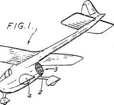
 Fig. 1
|
The motor 3 is shown in Figures 2 to 4. It comprises a hollow cylindrical casing made of aluminium with a closed front end 6 and an open rear end. The casing receives a solid gas-generating charge 7 in the form of a cylindrical pellet which fits closely inside the cylindrical bore of the casing. An igniting wick 8 is coiled on the end of the charge 7 and a wire gauze disc 9 is placed on the wick, which is led outwards through a gap in the edge of the disc 9.
A removable end cap 10 is built up from a central jet member 11, an outer plate 12, a backing plate 13 and an annular asbestos washer 14 interposed between the outer and backing plates, these components being held together by screwing the jet member into an internally threaded boss 15 on the outer plate 12. The cap 10 is held in position by five wire rods 16 having hook-shaped ends 17 which enter an annular groove 18 in the face of the plate. These rods 16 extend along the outside of the casing 5 and pass through holes 19 in a front plate 20 which has a central opening in which a boss 21 projecting outwards from the end 6 makes a tight fit so that the plate 20 is rigid with the casing 5. At their ends the rods 16 pass through bores in anchorage members 22 and the actual ends are turned round as shown at 23 to lie in sockets 24 in the members 22. Each rod is surrounded by a spring 25 which abuts against the plate 20 and one of the anchorage members 22.
|
|
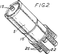
 Fig. 2
|
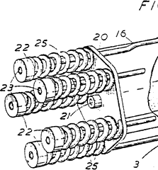
 The boss 21 has a threaded bore 26 which can receive the end of a bolt secured in the model aircraft so that the motor can easily be attached to or removed from the aircraft.
By pushing the anchorage members 22 while holding the casing 5, the rods 16 can easily be moved axially to allow the end cap 10 to be removed or put in position. Since the cap extends over the whole diameter of the casing. the insertion of a fresh charge 7 after the removal of the cap is a very simple matter.
The wick 8 is led out through the jet orifice in the member 11. When it is ignited it burns away, leaving the orifice clear, and ignites the charge 7. This then burns, generating gas which builds up to a high pressure in the compression chamber formed between the charge 7 and the cap 10 and escapes at high velocity through the jet orifice. producing a forward thrust on the aircraft by reaction.
|

|
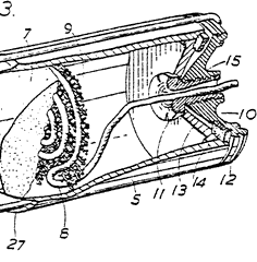
 Fig. 3
|
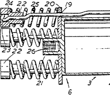
 The strength of the springs 25 is a matter of importance, as they must hold the cap 10 in its closing position so long as the motor is working satisfactorily but must yield to allow the cap to move rearwardly under abnormal pressure in the casing so that the gases can escape radially between it and the rearward end of the casing. In other words the cap and its mounting constitute a safety device by which the pressure within the casing is relieved if it exceeds a predetermined amount. It is found that satisfactory results are obtained if the springs 25 hold the cap in position under pressure up to about 100-150 lbs. per square inch but allow the cap to move to let the gases escape past it when the pressure rises to about 175 lbs. per square inch.
It is found desirable not to shroud the outlet of the jet orifice in any way. It is partly for this reason that the rods 16 run outside the casing to the forward end in the motor shown in Figures 2 to 4. In addition it is important not to expose the springs to the heat of the escaping gases, as this may cause them to lose their temper, and this is a further reason for making the rods extend forwardly.
|

|
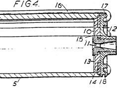
 Fig. 4
|
An important advantage obtained by constructing the motor in the way shown is that the only screw threads which just be machined are those between the orifice member 11 and the boss 15 and those in the bore 26, and all the parts can be made easily and cheaply. Another advantage is that no part of the safety device can be blown away by excessive pressure, so the motor is suitable for use by boys.
During flight a considerable amount of heat is generated and this has an important bearing on the construction of the casing 5. The charge will burn on attaining a temperature of about 200° C. When it burns the temperature rises rapidly to about 1000° C. It is necessary to prevent the wall of the casing from exceeding 350° C. at any point nearer the end 6 than the burning face of the charge, as otherwise the charge will burn unevenly down the side. The casing wall is therefore made thick enough around the rearward part of the charge to absorb the heat adequately but around the forward part or base of the charge the wall thickness is decreased to reduce the weight, as shown at 27. Alternatively, cooling fins may be made on the outside of the casing.
|
|
Another advantage is that no part of the safety device can be blown away by excessive pressure, so the motor is suitable for use by boys.
|
The motor shown in Figure [sic] 2 to 4 may be mounted in an aircraft, vehicle or vessel in other ways. For example, a metal clip 30 may be secured to any suitable part of an aircraft, vehicle or vessel 40 by two screws 31, as shown in Figure 5, and two of the anchorage members 22 may engage in a channel 32 formed by bending the end of the clip, the boss 15 entering a slot 33 in a lug 34 formed by bending up 45 the rearward end of the clip. Again, as shown in Figure 6, a lug 35 can be secured to the boss 21 by a screw 36 and can enter a slot 37 in an aircraft fuselage. Since the motor exerts a reaction thrust, it is enough in some cases simply to fit it into a socket without positively securing it there. For instance Figure 7 shows a model speed boat formed with a socket 39 housing a motor 3. Cooling becomes particularly important in such a case and there must be passages for cooling air between the wall of the socket and the motor and openings at the front of the socket through which air can enter these passages.
In a model racing car the motor 3 can be arranged in a socket above the back axle, as shown diagrammatically in Figure 3.
Many modifications may be made. Thus, as shown in Figure 9, an end cap 66 may be made movable against a spring provided at the rear of the casing. Here the casing 51 is reduced in diameter at the rearward end and formed with an internal flange 40 within which there is an opening 41. This opening is closed by a cap formed by a cup-shaped jet member 42 having a flange 43 which forms an abutment for a spring 44. A tubular member 45 is screw-threaded at one end to fit over the reduced end of the casing 51 and formed with an internal flange 46 at the other end, this flange forming the second abutment for the spring 44. Leakage of gas is prevented by an asbestos washer 47 interposed between the flanges 40 and 43 and compressed by the spring 44. The jet member 42 can move against the spring 44 to relieve the internal pressure and allow the gases to flow past the washer 47 and through the annular space between the members 42 and 45 if the predetermined maximum is exceeded; to allow the gases to escape freely from the annular space holes 48 are made in the flange 46. In this motor the charges cannot be introduced through the opening 41 so the forward end of the casing 5' is formed by a screw-threaded cap 49 which extends over the whole diameter of the casing.
In the motor shown in Figure 9 the 95 internal pressure is applied only to the inner end of the jet member 42, the area of which is less than that of the end cap 10 shown in Figure 2 to 4, so the spring 44 can be comparatively light. This spring is, of course, shrouded from the hot gases by the tubular wall of the member 42.
Having now particularly described and ascertained the nature of our said invention and in what manner the same is to be performed, we declare that what we claim is : -
1. A reaction motor of the type set forth comprising a. casing for the reception of a gas-generating charge in which a member containing one or more jet orifices through which the combustion gases are discharged is made movable relatively to the casing and is subjected to spring pressure such that it can move to allow the combustion gases to escape past it if abnormal pressure builds up in the casing but is held in position while the gases are escaping normally through the orifice or orifices.
2. A motor according to claim 1 in which the casing is cylindrical, the forward end of the cylinder is closed and the rearward end is constituted by a cap, the diameter of which is the same as the internal diameter of the casing and which is formed with a jet orifice, this cap being subjected to spring pressure so that if it moves rearwardly under abnormal pressure in the casing the gases can escape between it and the rearward end of the casing.
3. A reaction motor of the type set forth comprising a casing for the reception of a gas-generating charge in which an end cap containing one or more jet orifices through which the combustion gases are discharged is provided at the rearward end of the casing and is held in place by one or more springs disposed outside the path of the escaping gases and of strength such as to hold the cap in place during normal operation but to yield to allow the cap to move rearwardly and the gases to pass round its edge if abnormal pressure builds up in the casing.
4. A motor according to claim 2 or claim 3 in which the cap is engaged by hook-shaped ends of rods extending outside and parallel to the casing and surrounded by springs at the front of the casing.
5. A reaction motor substantially as described with reference to Figures 2 to 6 or Figure 9 of the accompanying drawings
6. A model aircraft. vehicle or vessel furnished with a reaction motor according to any of claims 1 to 5.
Dated this 25th day of October, 1945.
For the Applicants:
GILL, JENNINGS & EVERY,
Chartered Patent Agents,
51/52 Chancery Lane, London, W.C.2.
Leamington Spa: Printed for His Majesty's Stationery Office,
by the Courier Press.—1950.
Published at The Patent Office, 25, Southampton Buildings. London, W.C.2, from
which copies, price 2s. Od. each (inland) 2s. 1d. (abroad) may be obtained.
|
|
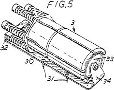
 Fig. 5

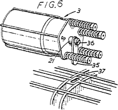
 Fig. 6

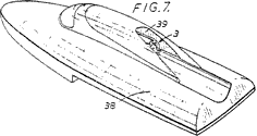
 Fig. 7


 Fig. 8


 Fig. 9
|
 |
 |
 |