|
|
|
|||
|
|
||||
|
|
||||
| Plan: Whirligig | ||||
|
|
HOME | SITE MAP | FORUM | CONTACT |
|
||
|
ABOUT | MOTORS | MODELS | ARCHIVE | HISTORY | STORE | FAQ | LINKS
|
|
|
|
|||||||||||||||||||||||||||||||
|
Whirligig by Bill Henderson
View or download plan for Whirligig The following is taken from Bill's Design Notes (W.H.H.15 1952, revised 5 May 2003) Jetex Helicopter – Whirligig |
||||||||||||||||||||||||||||||||
|
Designed and built for the Helicopter event at the 1952 Northern Heights Gala. It was inspired by the article on Jetex helicopters by F.G. Boreham in the Jan. 1951 issue of Aeromodeller. The design followed many of the details presented in that article, using a large diameter rotor at right angles to a shorter beam that carried a Jetex motor at each tip. The rotor blades were designed to auto rotate using the "delta 3 " concept of angled hinges near the root (as described by Boreham), which allowed the rotor to swing up, but the rotor blade incidence gradually became negative in the process.
It flew well in calm conditions, typically giving a 1 minute flight in evening air, using 3 charges in each motor. It was easy to launch by hand, but was very difficult to launch from rest, sitting on a launch pad, as was required at the Northern Heights Gala. The weather at the Gala was very gusty and the model was wrecked soon after launch, due to being tipped sideways by the wind. This article by Bill is reprinted from Frank Zaic's Model Aeronautical Yearbook 1953, p. 104 Jeticopter Design |
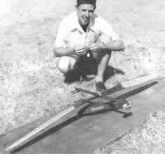 Bill Henderson with 'Whirligig' at the 1952 Northern Heights Gala
- Bill's personal collection
|
|||||||||||||||||||||||||||||||
Opinion varies as to the various sizes and weights etc. that are most suitable for each size
of motor but the table below gives a general idea of the majority opinion.
It is obvious with this form of modelling as with every other, that power/weight ratio is important and with fixed power motors, weight must be cut down as much as possible to get a better contest performance. The Span Loading is taken so it is proportional to the disc loading and is in figures more easily comprehended. The Rotor Center Section is usually about 28-35% of the Rotor Diameter. The Pitch Angle varies from model to model but generally use 15° on "50" and "100" models, and 12° on "200" to "350" models. The "delta 3" (full-size parlance for the system of skew hinge system for producing auto-rotation angle) can vary between 30° and 35°. The rotor centre section can be made from ply with hinges mounted in blocks at ends at approximate pitch angle. This is easier than building it up but it is heavier. Should anyone be a stickler for helical pitch they can build the outer rotor blades on a pitch angle jig, but generally fiat ones set at the approximate angle by the hinges on the centre section will be quite effective. These models will ascend fairly quickly and should descend on auto-rotation much more slowly, in fact in good thermal conditions they should be able to soar slightly and thus greatly enhance their performance. Ball races are not necessary in the head bearings but are strongly recommended on "200" and "35O" models, they being much more friction free than an ordinary journal bearing. The hinges used are universal on all sizes of jeticopters and so far no other satisfactory one has been thought of, but some improvements could possibly be made to lock hinge wire in place and yet allow it to be taken out for ease of transportation. |
||||||||||||||||||||||||||||||||
|
|
|
|||||||||||||||||||||||||||||||
|
|
|
|
|
|
|
|
Acknowledgements Design notes, article and plan: Bill Henderson |
|
|
|
|
ABOUT | MOTORS | MODELS | ARCHIVE | HISTORY | STORE | FAQ | LINKS |
|
|
Terms of Use
|
Queries? Corrections? Additions?
Please
contact us.
|
|