|
|
|
|||
|
|
||||
|
|
||||
| Plan: Super Mystère | ||||
|
|
HOME | SITE MAP | FORUM | CONTACT |
|
||
|
ABOUT | MOTORS | MODELS | ARCHIVE | HISTORY | STORE | FAQ | LINKS
|
|
|
|
|||||||||||||||
|
Constructing the Super-Mystère
Translated from Modèle Magazine, June 1955 Since we're now well aquainted with the best-known jet aircraft [preceding articles had covered leading jet aircraft of the period], let's go on to become aircraft manufacturers and undertake the construction of a flying model of the SUPER-MYSTERE. First, we'll acquire the building material we'll need. One sheet of A small flat board about 40 cm long and about 10 cm wide will serve us as our assembly area. |
|
|||||||||||||||
|
A number of thin pins, a razor blade, and a sheet of fine sandpaper sheet will do us for our tools. We'll use carbon paper to transfer the shapes of the formers onto the We'll put the plan on the building board and fix it there with drawing pins. Firstly, we'll make a fuselage half-shell following the method illustrated in the lower right-hand corner of the plan. We'll firstly set in place the lower strips of We'll cement in place the remaining strips alternately on either side of the centre strip. To make sure that we have a strong fuselage, we need to cement the edges of each strip together along their entire length, making sure also that each is cemented to the formers. The strips need to be narrowed at each end so that they fit closely against their neighbouring strips. Be prepared to adjust the position of the strips so as to produce a smoothly rounded shell. We must be careful not to lift the first half-shell off the building board before the cement is completely set. At that point, we can start gluing the other set of half-formers to their opposite numbers. We can then finish the fuselage in the same way as before. When everything is dry, take out the pins, and sand the shell smooth with very fine sandpaper, taking care not to apply too much pressure. The shaping of the cockpit is carried out in the same way as the fuselage. The dorsal spine, which continues the line of the cockpit, is cemented in position after being shaped to match the profile shown on the plan. The block for the nose piece is cemented onto former 1 before being shaped. It's much easier to shape it once it's in place. The whole fuselage is then resanded and doped. If you plan to use a Jetex motor to propel the plane, be sure not to leave out the piece of The wings can be built directly on the plan; since the airfoil is symmetrical, there's no separate drawing of the right wing, and the one drawing can be used for both wings. Slots are cut halfway into the trailing edge to receive the rear ends of the ribs. The wing tips are made of three laminations of 1/16" sheet and match the shape of the ribs. Since the ribs are biconvex you need to support the trailing edge during assembly with small packers so that the centerline of the ribs remains parallel with the building board. When the wing is quite dry, carefully round off the leading edge and sand down the trailing edge to its wedge shape. Each half-wing then is covered, doped and held firmly in place on the packers while drying, to prevent warping. The stabilizer and the rudder are cut from sheet and cemented together. If you want the smoothest possible finish on the fuselage, apply a mixture of talc and dope to the shell, allow to dry then lightly sand. The talc will fill the small crevices and after repeating the process several times, you'll have a perfectly smooth surface. When all the completed components are joined together, you should check that both wings are in line, without any variation in their incidence. The tail must be perfectly perpendicular, and the stabilizer must have the incidence shown on the plan. Paint the assembled aircraft in aluminium and apply markings. In its finished state, ready to fly, it will weigh about 28 grams. For the initial test flights, find a grassy field and wait for a perfectly calm day. Launch the plane gently, with its nose pointed slightly downward, and the Jetex motor empty. The aircraft should complete a shallow glide without dipping to left or right. If the plane rears up then dives nose first, it needs weight added to the front - a drawing pin should be sufficent in most cases. If on the contrary it dives directly to the ground, add weight to the rear. If it turns sharply to left or right, there's a difference in incidence between the two wings, or they're warped. Compensate by cementing a painted tab to the end of one wing. When it's gliding as it should, light the Jetex motor, wait until there's a steady thrust and launch the plane into the wind. It will ascend in wide circles, its speed quickly increasing. How long the flight lasts and how high it ascends depend on the care you've taken in building the model. |
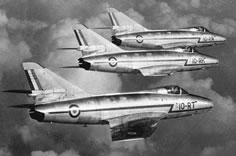 A patrol of full-size Super Mystères B2
- Agence Diffusion Presse
|
|||||||||||||||
|
|
||||||||||||||||
|
|
|
|||||||||||||||
|
Plan for Super Mystère
(A larger copy of the plan (GIF format) is also available to
view or download.) View translations of French terms used in model plans.  |
||||||||||||||||
|
|
|
|||||||||||||||
|
|
|
|
|
|
|
|
Acknowledgements - Article and plan contributed by Pierre Claudy - Translation from the French by John Miller Crawford |
|
|
|
|
ABOUT | MOTORS | MODELS | ARCHIVE | HISTORY | STORE | FAQ | LINKS |
|
|
Terms of Use
|
Queries? Corrections? Additions?
Please
contact us.
|
|