|
|
|
|||
|
|
||||
|
|
||||
| Plan: F-19 Stealth | ||||
|
|
HOME | SITE MAP | FORUM | CONTACT |
|
||
|
ABOUT | MOTORS | MODELS | ARCHIVE | HISTORY | STORE | FAQ | LINKS
|
|
|
|
||||||||||||||
|
F-19 Stealth
Reprinted from Aeromodeller, May 1987, pp. 265 ff. Ssshh… build a Stealth F-79! Get ready to light the fuse – we bring you John Emmett's super-secret fighter |
|
||||||||||||||
|
IT IS PERHAPS a bit speculative to call this a scale subject, as the only basis at present for thinking there is such a craft is a plastic kit and some well- substantiated rumours. Nevertheless there are some facts which you can ponder for yourself. First, there is a gap in the USAF `F' series between F-18 and F-20. Second, the Lockheed `Skunk' works are known to have produced prototypes of aircraft that are nearly radar-invisible. These prototypes are almost certainly moved from place to place inside Galaxy transport jets so that governs a maximum size of fuselage. Then it is reasonable to suppose there would be similarities to the known Lockheed SR71 Blackbird… A lightly loaded model such as this performs quite delightfully. Any stall is flat, gentle and accompanied by wing waggling, just like a well behaved paper dart. So far, my F-19 has proved quite crashproof too. What better reasons are there for building one? And remember, Scale Day at Old Warden is getting close… Building your fighter Construction is conventional, for a Jet-X scale model that is. We have provided labour-saving by showing you how to fit the parts onto a 1/ l6in. medium soft sheet. Make a relatively dark xerox copy of the layout and check that the copy is correctly sized, for some copiers are terrible in this respect. Brush the surface of the copy with white spirit and lay it face down over the balsa. Iron over it at medium heat, making sure it doesn't slip and you will have a ready-to- cut parts sheet. Pin down the wing surrounds W1 to W5 protecting the plan from adhesive with a layer of cling film. Cut L1 from 1/4 x 1/8 in. medium strip. Mark the angles of F3 and F4 onto it and pin down on the centre line of the fuselage, gluing to W5 at the rear. Next add F2 to F8. raising the wing surround off the building board with 1/16 in. scrap packing to allow F3, F4 and F5 to fit correctly. Fix the doublers L1A and add the seven 1/16in. sq. top stringers, chamfering them where they fit onto the wing surround. Make up the fins from 1/4 x 1/6in. and 3/16 x 1/16 in. strip with 1/16in. sq. cross pieces. Turn the now dry body over and fit F1 into place followed by the lower parts of F2 to F7; then add L2, F5A, the two 3/32 in. stringers beside the motor trough and the four 1/16 in. sq. stringers beyond that. Sand smooth and cover ahead of F5 with 1/32in. sheet, applied with the grain running longitudinally. Turn assembly over and sheet the top in front of F5, adding a triangular piece to form a cockpit fairing between F4 and F5. Don't forget the dummy air intakes. The nose block and fin supports (L3) are added last. Finish the body. It is then ready for sanding and covering in lightweight tissue. Water shrink and dope with two coats of '50/50' dope/thinners. The motor trough can be formed from a strip of note paper pressed into the gap between the stringers, gluing down to Li between the formers F5A to F8. Add the false keel L4 so you have something to grip for hand launching, followed by W6 and both T1s. The fins T2 must be pinned down to the building board after covering and doping so thay are not fixed to the body until the latter is finished. Finishing Here you can certainly use your imagination; after all, any reader knowing better than your designer – or you – is hardly likely to send in photographs of the full sized F-19 (please don't!). So go to town on the decoration using a light aerosol or airbrush finish to keep the all-up weight to below an ounce. Protect the motor trough between F5 and F6 with a piece of aluminium from a food container stuck on with a contact adhesive such as Evostik. The same material is ideal for the trim tabs. Screw the motor clip onto L1 through the aluminium using 1/4 in. countersunk woodscrews or small self tappers. The cockpit can be covered with two pieces of celluloid fore and aft of F3. Overnead projection transparencies are a great source of this material, although a slight gold or silver metallised window film would probably be more authentic. A metal film on the real canopy would prevent electrical signals from escaping from the cockpit instruments. First flight tests Stick any bits you have left over on where they look best, and check the centre of gravity with an empty motor in place. Don't let the CG move aft of the point shown unless you want some really wild missile runs; and aim for a straight, fast flat glide. You can get a lovely slow floating glide on these deltas, just like a landing Concorde but to start with you need to strike a balance between the glide and the power-on climb. Lighting the motor This is the most risky part of the whole affair, so hold the model vertically nose-up with the underside towards you while you face downwind. I use a cigarette lighter set at a very low flame setting to light the wick. Load with one pellet, wait for thrust to build and launch straight ahead into wind. Correct any looping tendency with a gentle turn induced by bending one trim tab or one side of WE upwards on the side towards which you wish to turn. A tight, spiralling turn may be reduced by the opposite process. When you are happy with the power climb, you can slow the glide right down. Flying with Jet-X All you need to carry with you when flying Jet-X goes into one pocket. I take a couple of motors, some fuel and pre-cut lengths of wick in a plastic bag, a small screwdriver with which to lever the wire clip and clean out the main case, and a small pair of pliers to hold a hot motor and to re-tension the wire clip. Don't forget the cigarette lighter for starting, plasticene for adjusting balance, a tube of glue for repairs if the worst happens – and that's it. Ssshh… keep it a secret! |
Three stages in building reveal that 'formers and stringers' construction is happily straightforward as there are no difficult contours to negotiate. 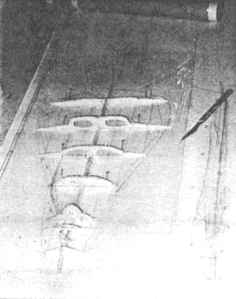 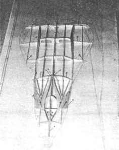 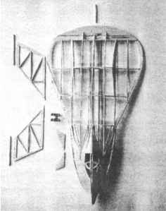 (Below) Under and over – the F-19 awaits its menacing all-black finish. Another possibility is 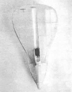 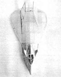
-
Aeromodeller, May 1987, p. 265.
|
||||||||||||||
|
|
|
||||||||||||||
Plan for F-19 Stealth
(A larger copy of the plan is also available to
view or download). |
|||||||||||||||
|
|
|
||||||||||||||
|
|
|
|
|
|
|
|
Acknowledgements - Article and plan from the MAAC archives, via Bill Henderson |
|
|
|
|
ABOUT | MOTORS | MODELS | ARCHIVE | HISTORY | STORE | FAQ | LINKS |
|
|
Terms of Use
|
Queries? Corrections? Additions?
Please
contact us.
|
|