|
|
|
|||
|
|
||||
|
|
||||
| Plan: Midge | ||||
|
|
HOME | SITE MAP | FORUM | CONTACT |
|
||
|
ABOUT | MOTORS | MODELS | ARCHIVE | HISTORY | STORE | FAQ | LINKS
|
|
|
|
|
|
|||||||||||||||||
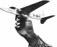
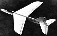
THIS MONTH’S model is a scale replica of one of the most beautiful British fighters now flying—the fascinating new private venture Folland Midge. As with the other “flying scales” in this series (Swift and Skyray), power is supplied by a ¼ ounce Jetex 50 motor and the building plans are shown full size. However, this latest design has the best performance of the three, since a cambered type wing is featured and a catapult launching method enables altitude to be gained—while the jet-thrust is actually building up. Construction is quite straightforward, but for those who are new to model building, we shall cover the various stages in detail. Start by carefully selecting good quality
The Fuselage
|
|
|||||||||||||||||
|
|
|
|||
|
Push a pin into the fuselage (D) at the catapult notch position and mark the location of the Jetex mounting clip. Trace the cabin and “G-39-1” number (shown in solid black) on to greaseproof paper, then tape the latter over two layers of black tissue and cut out with a sharp razor blade. Carefully dope the tissue pieces in place and add the, remaining markings (jet intakes, UC doors, etc.) in soft pencil. Go over these lines with a ballpoint pen and put aside until the ink dries, to avoid smudging. Cement piece F to the right side of the fuselage—so that the “clip holes” are covered.
Flying Surfaces
Mark the carving lines on the wing panels (A) with a ball point pen, then carve away the surplus wood (on top only) at the leading and trailing edges, with a razor blade. Finish off to the correct aerofoil section with garnet paper, sanding away the carving lines last of all. Sand the roots to a slight angle, to allow for the dihedral, then cement the dihedral brace (B) in the slot in one wing panel. When dry, join the other panel to the first. Mark the control surface outlines in soft pencil—on the wings, tailplane (C) and fin (E)—then go over them with a ball-point pen. Cut out the portion of the fuselage shown in dotted lines and shape the lower edge to conform to the wing aerofoil. Cement the wing in place—checking the alignment in the top and front views—and hold secure with pins, until dry. Cement the fuselage scrap back in place over the wing and slide the tailplane in the rear slot. Cement a matchstick in the slot in the right wing tip and a paper clip under the same tip to compensate for the offset motor weight. Screw the mounting clip to the left side of the fuselage and cement two 1 in. x 2½ in. pieces of asbestos paper to the fuselage and left wing root, behind the clip. Now slide the loaded Jetex 50 motor into the clip and check that the model balances level when suspended by a pin pushed into the fuselage top, above the black arrow marked “balance”.
Flying
With the loaded motor in place, face into wind, hold the model at the balance point and launch it firmly ahead on a slightly downward flight path. If the model dives, carefully bend up the trailing edges of the tailplane about When the glide is correct, light the wick, wait a few seconds and throw upwards at an angle of about 30 degrees. For maximum duration, use a catapult launch, releasing the model right after lighting the wick. The catapult should consist of 10 feet of |
- RAF Flying Review, Feb. 1955 (p.37)
|
|||
|
|
|
|||
Plan for Midge
(A larger copy of the plan is also available to
view or download). |
||||
|
|
|
|||
|
|
|
|
|
|
|
|
Acknowledgements - Article and cleaned-up plan contributed by Gareth Paterson |
|
|
|
|
ABOUT | MOTORS | MODELS | ARCHIVE | HISTORY | STORE | FAQ | LINKS |
|
|
Terms of Use
|
Queries? Corrections? Additions?
Please
contact us.
|
|