by Aeromodeller Staff
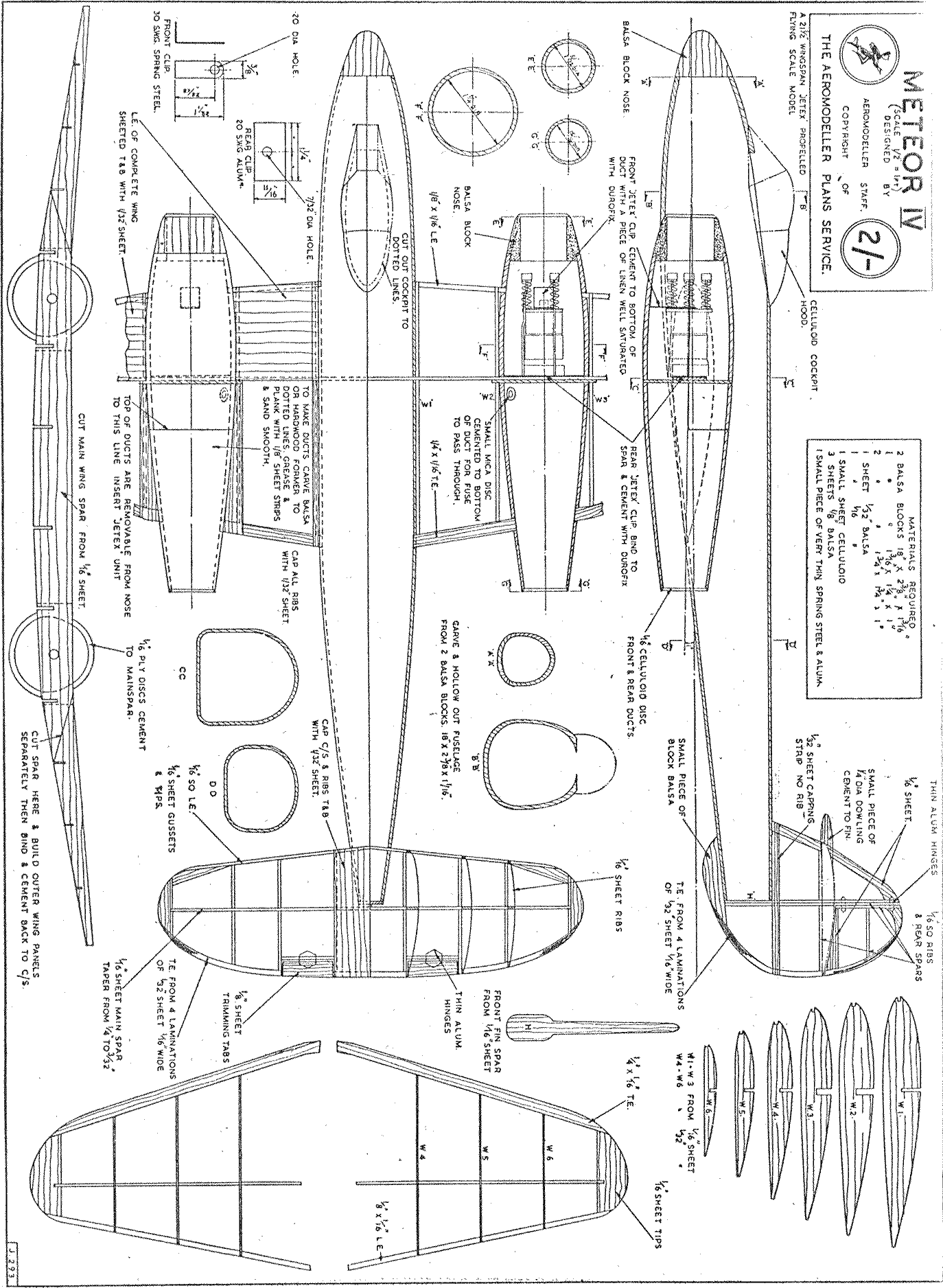
The Fuselage. This is carved from a block of hard balsa measuring 17 7/8 ins. x 2 3/8 ins. x 2 1/8 ins. This is cut vertically in half and temporarily rejoined with a layer of tissue in the joint, this to facilitate separation after the external carving has been completed. The inside is hollowed out, the thickness forward of the C.G. (which is on the main spar) should be 1/8 inch. Aft of this position the fuselage should be taken down as thin as possible compatible with strength. The two halves may be joined together with Durofix pre-gluing for strength.
Ducts. A mould should be made to the inside dimensions of the duct shown on the drawing and the duct nose block tacked on with cement. The mould is well greased with petroleum jelly or vaseline and planking is commenced with medium soft 1/8 square balsa. This may be carried out with a casein glue such as "Casco", which should be left to set for 24 hours. When dry make a neat cut around the duct in the spar position, then carefully remove the two halves. Celluloid rings are cut to form a clean edge to the duct orifices also to strengthen these points. Finally attach the mica, discs on the duct sides which carry the fuses. Our heading photo shows the Meteor and Zephyr models in flight with a sectional view of a typical unit inset. Above are various flying shots of the Meteor demonstrating its scale appearance.
Wing and Ducts. Cut all spars and ribs to the drawing. The main spar is threaded through the fuselage, lined up and glued securely with Durofix. The two root ribs on either side of the fuselage are glued securely and perfect alignment assured. It should be mentioned that extreme care in building is most essential as the slightest inaccuracy in the structure will prove quite disastrous in flight. The centre section should now be completed with the exception of the sheet covering. The ducts are then fitted, lined up and glued fore and aft of the ply former. The extension planes are built on the board and aligned and glued to the main spar, the main spar spliced joints being covered with tissue saturated in Durofix. The leading edge is then sheet covered with 1/64th sheet balsa.
Tailplane, Fin, Elevator and Rudder. These are of straightforward construction and require little explanation. Tailplane ribs are of 1/16th sheet and trailing edges of rudder and elevators are of laminated balsa using a. casein glue. All hinges are of very thin tinplate or aluminium.
Fitting the Jet clips. This job has to be done extremely accurately and to ensure perfect alignment two card templates are cut to fit in the front and rear duct orifices. In the centre of each is drilled a hole to take a piece of steel rod or straight dowelling. This is used as a jig for perfect alignment of the two metal clips.
Finishing. The model is covered in rag tissue with the exception of the fuselage. Water spray and apply two coats of 50-50 thinners, dope and colour trainer yellow.
Flying. Long grass is most essential for preliminary trimming. First see that the C.G. is over the main spar and with all controls set at neutral try a glide, trim until the glide is flat. A word of warning, the glide is very fast therefore good launching is essential Flying is a two man job. One person lighting the fuses, which come through the mica disc on the duct sides, the other actually launching. Do not launch the model until your assistant reports that both jets are expelling satisfactorily.
