The invention will be more clearly understood by reference to the accompanying drawings in which:
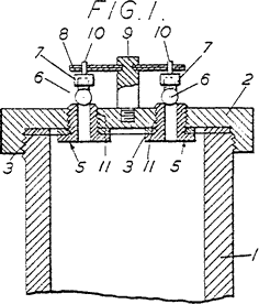
Figure 1 is a longitudinal section through one motor according to the invention on the line X-X in Figure 2;
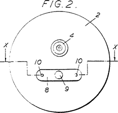
Figure 2 is an end view of the motor shown in Figure 1; and
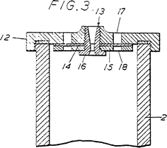
Figure 3 is a central longitudinal section through another motor according to the invention.
In the construction shown in Figures 1 and 2, there is a cylindrical casing 1 closed at the forward end and provided with a screw-threaded cap 2 at the rearward end, a washer 3 being interposed between the cap and the casing. A single jet orifice 4 is formed eccentrically in the cap and so are two openings 11 which are tapped to receive tubular valve fittings 5. The outer ends of these are formed with reamered orifices having sharp edges against which steel balls 6 are pressed by cups 7 carried by a leaf spring 8 which is held in a mounting 9 carried by the cap 2. This mounting is a stud in line with and midway between the valve fittings, and the leaf spring extends from it over each fitting and receives a pin 10 extending up from each cup 7. The mounting 9 is made of heat-insulating material and the cups 7 are lined with asbestos so as to minimise the transmission of heat to the spring. It is found to be important to harden the steel balls and to reamer the valve seats in the fittings because in this way a knife edge seat is formed and is still gas-tight on closing after the balls have moved to relieve abnormal pressure. The knife edge helps to cut through any dirt that may lodge on the valve seat.
In the motor shown in Figure 3, a casing 2 of the same type is used and receives a screw-threaded end cap 12 into the middle of which an orifice member 13 is screwed. A thin frangible disc 14 is held against the inner face of the cap by a backing plate 15, which is itself held in position by a flange 16 on the orifice member 13. When a frangible disc is used, difficulty arises in making the disc both weak enough to yield directly the pressure rises and yet sufficiently resistant to heat to withstand the normal conditions. It is found that the requirements are satisfied if the frangible disc 14 is made of thin asbestos paper, say 0.02 inches thick, and registering holes 17 and 18 are made in the cap and backing plate respectively, these holes being individually small.Thus, there may be four holes in the cap and four corresponding holes in the backing plate and each hole may be, say, 1/16th of an inch in diameter. It is found that the unsupported parts of the disc in register with the holes in the cap and backing plate will then collapse under a pressure of about 175 lbs. per square inch. Naturally the frangible disc may be made of any other appropriate heat-resisting material, and its thickness and the size of the two sets of holes depend upon the exact strength of the material used.
What we claim is: -
1. A reaction motor of the type set forth comprising a casing for the reception of a gas-generating charge with one or more jet orifices for the discharge of the combustion gases in which a safety device controlling one or more openings separate from the jet orifice or orifices and consisting either of a spring-loaded valve, or of a frangible disc or the like, is provided to allow any abnormal pressure to be relieved.
2. A reaction motor of the type set forth comprising a casing for the reception of a gas-generating charge with one or more jet orifices for the discharge of the combustion gases in which a spring-loaded valve separate from the jet orifice or orifices is provided to relieve the pressure within the casing should this rise above a predetermined value, the spring or springs being disposed outside the path of the gases.
3. A motor according to claim 2 in which the valve comprises hardened steel balls engaging seats with knife edges.
4. A motor according to claim 1 in which the safety device is a frangible disc made of asbestos paper or the like held in position between the inner wall of the rearward end of the casing and a backing plate formed with holes which register with holes made in the rearward end of the casing.
5. A rocket motor according to any of the preceding claims in which there is a single jet orifice made eccentrically in a plug or the like screw-threaded into an opening in the rear end wall of the casing and another eccentric opening is provided in the same end wall and is closed by the spring-loaded valve or thin disc.
6. A rocket motor of the type set forth constructed substantially as described with reference to Figures 1 and 2 or Figure 3 of the accompanying drawings.
For the Applicants:
GILL, JENNINGS & EVERY.
Chartered Patent Agents,
51/52 Chancery Lane, London, W.C.2.
Printed for Her Majesty's Stationery Office,
by Wickes & Andrews Ltd., E.C.4. 89/244 — 1953
Published at The Patent Office, 25, Southampton Buildings. London, W.C.2, from
which copies may be obtained.
|
|

 Fig. 1


 Fig. 2


 Fig. 3
|