[…]

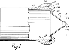
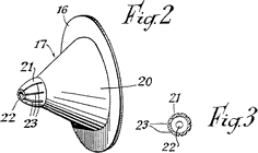
The main element of the cap is a truncated cone, at whose point there is a nozzle 21, which forms the jet orifice itself. Internal entry to the nozzle is through an opening whose diameter is approximately one quarter the diameter of the casing 10. The nozzle 21 is tapered to the actual orifice 22, and is cross-sectionally in the shape of a half ellipse. Cut lengthwise into the exterior of nozzle 21 are deep grooves or notches 23 (Figures 2 and 3) which extend back from the actual orifice. In the event of internal pressure in the casing 10 exceeding the normal operating pressure, the wall of nozzle 21 breaks apart into segments and expands outward, opening up in the fashion of flower petals, resulting in an enlargement of the orifice and safely lowering the pressure in the casing 10. Subsequently, the nozzle can be speedily and simply replaced. […]
(Der Hauptteil ist durch einen Kegelstumpf gebildet, an dessen kleinerem Ende sich der Düsenteil 21 anschließt, der die eigentliche Strahldüse bildet. Am Eingangsende ist dieser Düsenteil mit einer Bohrung versehen, deren Durchmesser annähernd ein Viertel des des Gehäuses 10 beträgt. Der Düsenteil 21 verjüngt sich progressiv bis zu der kleinen Düsenaustrittsöffnung 22. Hierdurch erhält der Düsenteil 21 im Längsschnitt die Form einer Halbellipse, wobei die Düsenachse mit der großen Ellipsenachse zusammenfällt. Auf dem größten Teil des Düsenteiles 21, und zwar auf dessen Außenseite, befinden sich Kerben oder Nuten 23 (Fig. 2 und 3) die sich in Längsrichtung erstrecken und die Sollbruch-Bereiche dieses Teiles der Düse bilden, die bei einem Innendruck in dem Gehäuse 10, der den Normalarbeitsdruck weit überschreitet, brechen. Hierbei weiten sich die Segmente der Wand des Düsenteiles 21 zwischen den Sollbruch-Stellen nach außen blütenartig auf und bewirken eine Vergrößerung der Austrittsöffnung, so daß sich der Druck im Gehäuse 10 ohne Gefahr für die Düsen und das dazugehörige Gerät vermindern kann. Die Düse kann hiernach leicht und schnell auf einfache Weise ersetzt werden.)
|
|

 Fig. 1

In the event of internal pressure in the casing 10 exceeding the normal operating pressure, the wall of nozzle 21 breaks into segments and expands outward, opening up in the fashion of flower petals


 Figures 2 and 3
|