Between the back plate 10 and the inside face of the cap there is fitted an annulus 17 of asbestos paper which may be of any suitable thickness for example 0.012 of an inch thick or 0.02 of an inch thick, depending upon the pressure at which relief is desired. For example, the thickness of the annulus can be such that it will fracture at a pressure of about 50 pounds per square inch or more depending upon the design of the motor and the pressure of the operating thrust.
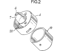
The screw threading 3 may if desired take the form of three or more lugs 19 mounted or formed on the outer surface of the motor casing 1 engaging with lugs 20 on the inside of the cap 4 the lugs on one or the other or both having inclined faces up which the ether lugs ride. This is shown in figure 2.
|
|
[T]he thickness of the annulus can be such that it will fracture at a pressure of about 50 pounds per square inch or more
|
For convenience it is preferred for threads on the cap 4 and the casing 1 to be rolled into the material.
Conveniently, the screw threading or other means for securing the cap to the casing is such that in the event of any one [sic] attempting to insert a diaphragm of thicker material, for example a metal annulus, the screw threading or other securing means will not engage.
When the motor is in use and the jet becomes clogged pressure builds up in the casing 1 until the asbestos paper annulus 17 spanning the holes in the cap and the apertures 11 in the back plate 10 bursts giving an immediate relief of pressure in the casing 1.
In order to put the motor into working operation again it is only necessary to remove the back plate 10, insert a new annulus 17 of asbestos paper or other frangible material, and reinsert the back plate 10 and screw the cap 4 home upon the casing 1.
WHAT WE CLAIM IS:
1. A rocket motor provided with a device for relieving any abnormal pressure in the combustion chamber thereof, comprising a frangible element held in position between the inner wail of the rearward end of the casing of the combustion chamber and a backing plate formed with holes which register with holes in the rearward end of the casing, the backing plate being held positively around its periphery against the inner wall.
2. A motor as claimed in Claim 1, wherein the. frangible element and the backing plate are held in position by a cap which is secured to the casing, and wherein the jet orifice of the motor is located in the cap.
3. A motor as claimed in Claim 2, wherein the cap is screwed, or otherwise releasably secured to the casing so that the frangible element is readily replaceable in the event of the element being fractured.
4. A motor as claimed in Claim 1, 2 or 3 wherein the frangible element is constituted by an annular disc having a through bore for the propelling gases to be fed to the jet orifice of the motor, the disc being formed from asbestos paper or other material which may be made to fracture at or above a predetermined pressure.
5. A motor as claimed in Claim 2, 3 or 4, wherein the means provided on the cap for releasably securing same to the casing is such that if the thickness of the frangible element exceeds a predetermined value the cap can not be secured to the casing.
6. A motor for having a device for relieving pressure in the combustion chamber, substantially as hereinbefore described with reference to Figure 1 or 2 of the accompanying drawing.
For the Applicant:
ARNOLD TICKNER,
Chartered Patent Agent,
Alexander House,
239/241, Shaftesbury Avenue,
London, W.C.2.
Leamington Spa: Printed for His Majesty's Stationery Office,
by the Courier Press.—1963.
Published by The Patent Office, 25, Southampton Buildings, London, W.C.2, from which copies may be obtained.
|
|

 Fig. 2
|