|
|
|
|||
|
|
||||
|
|
||||
| ARCHIVE: Jetex Scale Models | ||||
|
|
HOME | SITE MAP | FORUM | CONTACT |
|
||
|
ABOUT | MOTORS | MODELS | ARCHIVE | HISTORY | STORE | FAQ | LINKS
|
|
|
|
|||
|
JETEX POWERED FLYING SCALE MODELS
By Phil Smith Chief Designer to Model Aircraft (Bournemouth) Ltd., Makers of "Veron" Kits. Reprinted from the Aeromodeller Annual, 1951, pp. 104-9 |
||||
|
SINCE the advent of the Turbo-jet engine in full size aeronautics, the prototype aeroplane modellist (or free-flight scale fan) has found himself with a mode of propulsion that has defied emulation in the miniature sense and within the bounds of the average pocket, with the exception of the firework type rocket and, of course, Jetex. It cannot be denied that there will in future years be very few full size aircraft powered by the conventional airscrew for the modellist to model and unless some genius designs a miniature turbo-jet at a price to fit the austerity pocket of the era, we shall all be modelling "oldies" with the same reverence we nowadays accord to '14-'18 types. However, Jetex power is a step in that direction, enabling us reasonably to reproduce in miniature the flight and form of the beautifully streamlined and contoured supersonic aircraft of this Atomic age. |
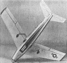
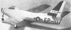 One of Phil Smith's Jetex 50 powered "squirts" – the Veron Sabre
-
Aeromodeller Annual, 1951, p. 104
|
|||
|
My own herewith recorded experiences in developing a small range of Jetex 50 powered "squirts" [see above right] will, no doubt, prove of interest to anyone intending to try this type of model, but must not, however, be taken as rule. The first mistake I made with Jetex power was grossly to over-estimate the power available when relating scale designs to the same comparative size of Jetex duration model. It is virtually impossible to emulate the streamlined contours of a modern fighter with anything but formers, stringers, and laminated balsa construction, a mode which will no doubt give something like 45 to 65 per cent, more weight for the same span as compared to the conventional four-square longeron type of fuselage and common wing construction. To explain this more clearly, Mr. P. B. Allaker's 1950 Jetex Contest winner [see right] was 30-in. span and weighed only 2¾ ozs., including a Jetex 200 (motor weight 1.125 ozs. uncharged). I take my hat off to any modellist who can produce a scale model, within the meaning of the word "scale", of 30-in. span to weigh less than 4 to 4½ ozs. complete with the 200 size motor. I must admit that at least 10 per cent. of the extra weight will be taken up with the extra cockpit cover, transfers, insignia, and extra coloured finish as is so normally (and liberally) applied. Therefore any scale model powered by Jetex would (for the average aspect ratio found in jet types) have to be:
The second mistake I made in assessing the virtues of a Jetex motor was the "constant thrust" theme as expounded by the manufacturers, Messrs, Wilmot Mansour and Co. Ltd., for admittedly, the thrust is pretty even except for a slight gain in power as the unit heats up, but the fact that the makers state that "jet motors are most efficient at high speeds" gives a clue to the fact that once airborne, all Jetex models invariably accelerate. They continue to do so to a point where any slight building discrepancy such as wing warp is accentuated to the inevitable and final demise of the model. In other words, when building models of prototypes originally designed with little or no inherent stability, build accurately so that no disturbing balance (especially laterally) or other mal-set-up will detract from the safe flight characteristics of the model. With gliders and rubber models you can sometimes get away with warps, but never in a Jetex model. |
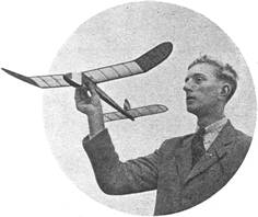 P. B. Allaker's 'Little Stinker' – the 1950 Jetex Contest winner
-
Aeromodeller, Feb. 1951, p. 85
|
|||
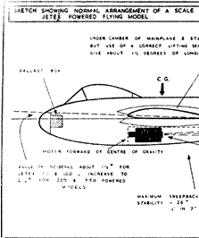
The C.G. ought not to be too low, but raised as near to the centre of resistance of the model, or, better still, on the thrust line with the thrust line high in the design. In scale designs, however, such a set-up is not easily found. As noted earlier, former, stringer, and tissue structures are the only ones which will give reasonable scale contours with light weight. Solid balsa bodies are out so far as Jetex is concerned. |
|
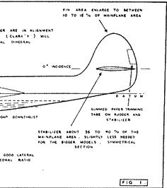 Fig. 1 Normal arrangement of Jetex scale model
-
Aeromodeller Annual, 1951, p. 104
|
||
|
So much for the basic structures. Positioning the Jetex units usually has its attendant detraction from scale effect. The natural place would he in the tail end of a model, but the extra ballast necessary in the nose would be prohibitive for the power generated. Therefore it must be amidships and one quite satisfactory way of fitting the motor unobtrusively is within a trough along the belly of the fuselage. A bit of "designer's licence" may usually be permitted so that the fuselage contour (usually round or oval) can be dropped to hide the width and depth of the trough. This trough then permits free access for fitting, re-charging the motor and replacement in the clip. It enables re-positioning of the clip for balancing purposes. It also permits a free flow of air past the jet to encourage maximum thrust and cooling. Jetex motors are at their best when air is permitted to flow quite freely past the jet cap so that the jet efflux impinges upon air flowing for 360 degrees around the circumference of the unit. I always feel that far greater efficiency would result if the rear cap of a Jetex were "coned" to a point - the point being no more than the actual jet orifice. The difficulty attending such a design of unit is obvious from a production point of view. |
 Underside of Veron 'Sabre', showing motor trough
-
Aeromodeller Annual, 1951, p. 104
|
|||
|
The reaction of an underslung motor invariably causes a nose-up moment which unfortunately, not only encourages climb, but as the speed increases, a looping tendency. This sometimes can be overcome by imparting "downthrust" to the jet unit. This business of "up" and "down* thrust usually generates controversial thoughts within the mind of the novice, but we must remember that thrust in a Jetex motor is the "reaction" created within the unit body; thus if a jet efflux is pointing upwards, and backwards, the "reaction" for the unit body is downwards and forwards (or downthrust) and vice versa. See Fig. 2. So for an underslung motor, downthrust (jet tilted upwards towards the tail) will stop the oscillatory flight or looping tendency. By far the best position for the jet would be in line with the centre of resistance, but scale considerations generally obviate this. Occasionally, as with the French Turbo-jet Assisted Sailplane, the
"Fouga-Cyclone"
or latterly-called "Sylphe", the jet unit does come above the centre of resistance, creating a very stable flight set-up without tendency to spin. However, there is a nose-down urge as the speed increases, which can be offset by imparting a very little up-thrust (jet pointing downwards and backwards). Incidentally, a little model of this machine, the first I built of a series, is perhaps far more stable, both laterally and longitudinally than any other I have built. Although only powered by a Jetex 50, the span was 30 in, because of the high aspect ratio. A pal of mine flies his with a 100 unit and has great fun. Lining the trough with thin cartridge or art paper, will overcome any burning tendency by the hot gases. When we recall that the greater percentage of the gas is steam, we can then no doubt understand why there is generally so very little charring of the structures in close proximity, even doped tissue. As long as there is reasonable space about the unit casing, as much as the normal clip will allow, charring will not take place, even should the casing become too hot to touch. Positioning of the unit in relation to the C.G. is also interesting. With underslung motors the unit should be in front of the C.G. of the airframe. The effect of this is that, in powered flight, the extra weight forward will tend to keep the nose down as the model accelerates and the lift generated by the mainplane increases until the charge is expended; then, in the glide, the airframe C.G. returns to its normal position as the charge burns away. The foregoing statements will therefore accentuate that the models must at all times be balanced and thoroughly glide tested with an uncharged motor in place. It must be noted that individual thrust settings will have to be made with individual models. Postcard thickness shims under the mounting clip to create extra up or down thrust settings, are all that are required to produce a variance between climb and level flight. This variable flight speed factor usually calls for symmetrical or flat section tailplanes. The short tail moment arms of scale models in relation to duration types are such that lifting section tails create longitudinal instability and delicate settings between the "power-on" and "power-off" flight trim. In fact the tailplane should be a stabilizer for the mainplane and no more, about 35 to 40 per cent, of the mainplane area, usually considerably more than true scale proportions. The longitudinal dihedral between wing and tail is usually incurred by the cambered section of the wing when we remember that the wing datum line is calculated from the point of curvature of the leading edge to the tip of the trailing edge. On a Clark Y section, this is usually about 1½ degrees and is quite sufficient on a Jetex 50 powered model or at the most, another 1 to 1½ degrees can be imparted for the heavier models when powered by Jetex 200 and 350 units. In other words, with the undercamber of a Clark Y section flat with the tailplane, there is in reality about 1½ degrees of longitudinal dihedral, and more, up to 3 degrees, may be added for heavier models. In any case, extra longitudinal trim can be gained by small gummed paper tape trim tabs set along the trailing edge of the tailplane and incorporated within the outline shape. Similarly, lateral and directional trim may also be had when set up along the wing tip and fin trailing edges respectively. In test flying, a gentle turn should be achieved by rudder trim during the power run. A turn will invariably eradicate a stall, for once a Jetex model points its nose down, the result is either a dive straight in or a violent oscillatory flight. One scale model that would need perhaps less fin area than the prototype, would be the Russian M.I.G. 15. The fin and tailplane are so highly located in relation to the thrust line that spinning tendencies are bound to be a heritage of a scale model which was not accurately trimmed and balanced. A better design by far, is the Lavochkin 17 with reasonable fin area and a high wing placing. Most other prototype designs therefore, usually require more fin area; that designed into most modern jet designs is totally inadequate for model use. The reduced fin areas on jet fighters is no doubt due to the absence of torque reaction, a feature which, in the Jetex scale models, considerably eases their trimming for flight. The amount of fin area to be added cannot he generalised, but is best arrived at by trial and error under flight conditions. Let it be said that swept-wing types, such as the Sabre, require less than the conventional wing types as with the Thunderjet; dihedral should be about 1 in. for every 10 in. span each side of the fuselage. |
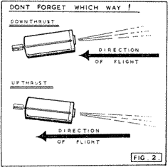 Fig. 2 Upthrust v. downthrust
-
Aeromodeller Annual, 1951, p. 104
|
|||
It has always seemed that Jetex in Scale Control Line would be most satisfying, but to power a 30 in. model of an "Attacker" or similar, nothing less than a 350 unit would give anything like the velocity for a stunt performance. Firstly, the duration of standard charges (3 in a 350 unit) would not be great enough (38 secs.) and at present, far too costly to run in comparison to the more orthodox diesel motor. I would however, like to see a long 350 size unit capable of housing say 10 standard charges - the overall length would he no more than 7½ in., weight 6½ ozs. and the duration about two minutes. I wonder how many people have ever seen a Jetex unit "escape" from its mounting clip and continue on its own in flight - the speed is something to be marvelled at. It may quite well be that a Jetex 350 unit in a 15 in, span control line model of, say, the Lavochkin 17, weighing 1½ ozs. airframe weight, would fly somewhere in the region of 150 m.p.h. Mr. F. R. Payne claims he once calculated that the muzzle velocity of a Jetex 350 unit was 2,450 m.p.h. and for the average thrust to be just over 5 ozs. It would seem therefore, that except for the cost and more elaborate re-fuelling technique, Jetex may yet be accepted as a medium for powering small scale Control Line models. |
|
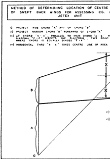
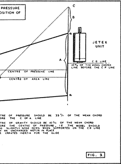 Fig. 3 Method of determining CP with sweepback
-
Aeromodeller Annual, 1951, p. 108
|
||
|
The fitting of Jetex as propulsive units to the rotors of model helicopters, is a "natural". Much has already been written about this type of model, but it must he acknowledged that this mode of power is far superior to rubber motors for turning the rotors. Rubber motors require such a long length to give a suitable duration, that the resultant fuselage (to wit – stick helicopters) completely rules out scale dimensions. Some modern helicopters have small ram-jets upon the rotor tips, but although it is known that Jetex units so placed can rarely be synchronised and balanced, this has quite easily been overcome by fitting the units to a transverse beam of ply or similar material as in the Jeticopter designs. This, coupled with a simple system of angular hinge lines for auto-rotation of the blades, means that model helicopter design has now assumed more normal proportions to scale and near scale. At this year's Northern Heights Gala Day, second place in the helicopter trophy was taken with a twin Jetex 350 powered helicopter, which was as near scale as one could wish. Its flight of 2 mins. 51 secs. means an autorotational glide of some 2 mins. 16 secs., which is better than most scale rubber jobs. |
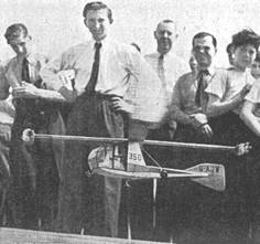 Ward's second placed Jetex 350 helicopter, at the 1951 Northern Heights Gala
-
Aeromodeller Annual, 1951, p. 109
|
|||
|
|
||||
|
|
|
|||
|
|
|
|
|
|
|
|
Acknowledgements Article and illustration sources: Roger Simmonds and MAAC archives via Bill Henderson |
|
|
|
|
ABOUT | MOTORS | MODELS | ARCHIVE | HISTORY | STORE | FAQ | LINKS |
|
|
Terms of Use
|
Queries? Corrections? Additions?
Please
contact us.
|
|